Holes & blind threads
Separate bore depth, full thread depth and fastener engagement.
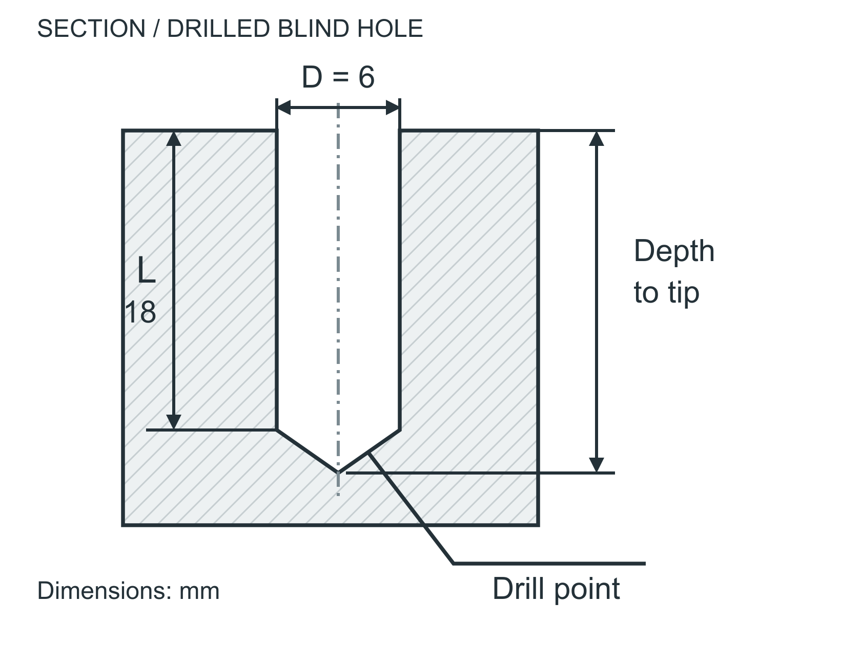
L stops before the drill point
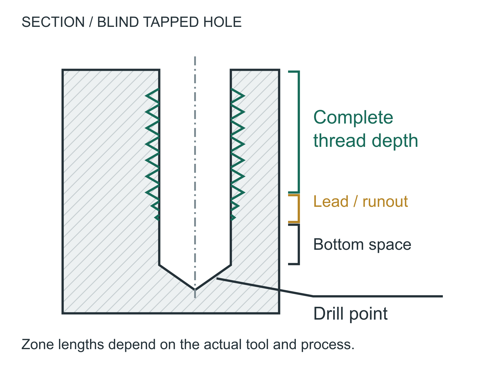
Complete thread first, tool allowance below
Hole ratio = full-diameter depth / bore diameter
18 / 6 = 3:1 | 60 / 6 = 10:103Check the assembled joint
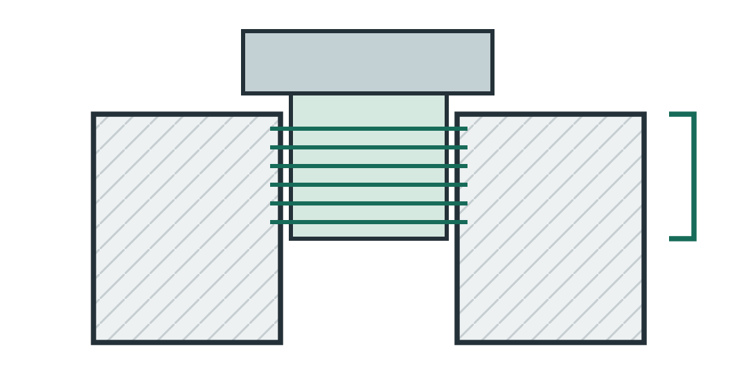
Engagement is the overlap of mating threads, not drilled depth. Required overlap depends on loads, materials and the fastener.
CAD: check bolt overlap in the assembly.
04Give chips an exit
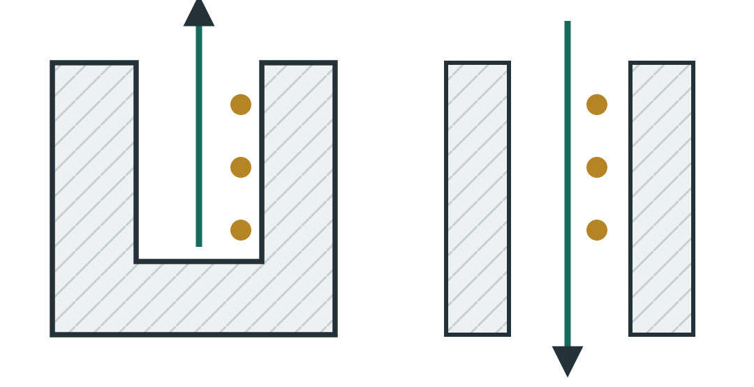
Blind and through holes need different chip strategies. Tool geometry, coolant and cutting cycle must match the actual hole.
CAD: use through holes where function allows.
05Use available sizes when suitable
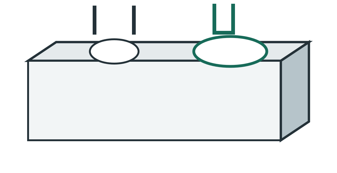
Standard drills can simplify tooling. A required fit may still need reaming or boring; nonstandard sizes do not always need interpolation.
CAD: keep the required fit, not an arbitrary size.
06Make passages cleanable
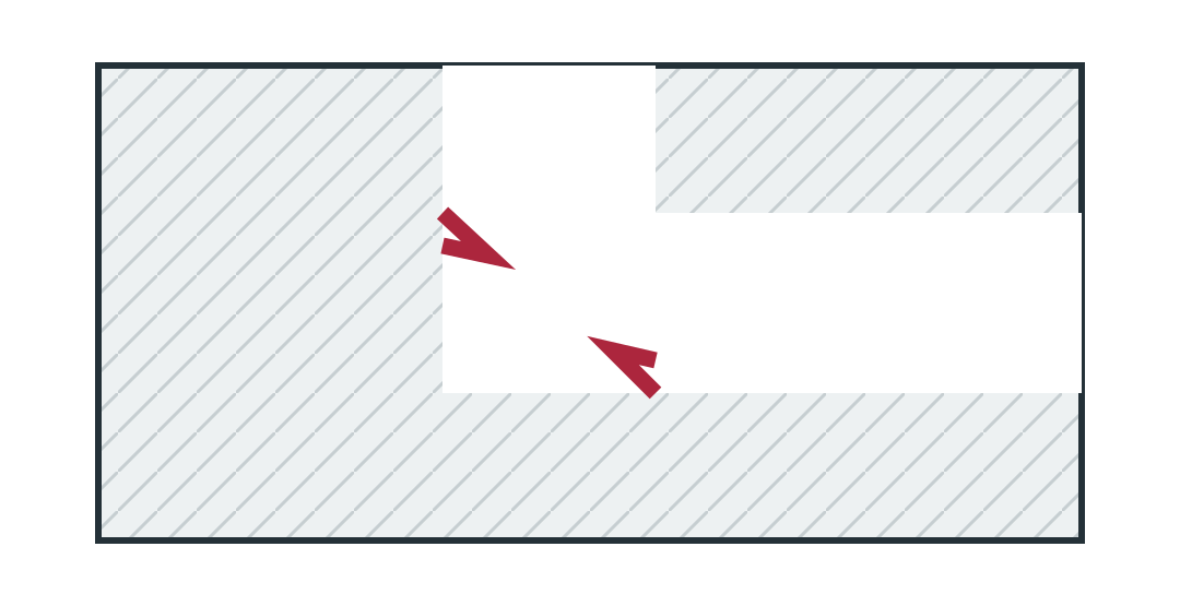
Cross holes can leave burrs inside the part. Include access for deburring, cleaning and verification of critical intersections.
CAD: locate intersections with cleanup in mind.
Specify complete usable thread depth. Set lead, runout and bottom allowance using the selected tool and chip strategy.
BEFORE RELEASE Protect fit, loads, sealing and required material sections when changing geometry.
- State thread standard, size, pitch and class.
- Distinguish through holes from blind holes.
- Dimension required complete thread depth.
- Confirm actual mating-fastener overlap and loads.
- Allow tool-specific bottom clearance.
- Review intersection burrs and cleaning access.