Engineering library

Engineering · DFM

CNC Design for Manufacturing

Pockets, threads, thin walls and critical interfaces. Practical design tradeoffs, dimensioned examples and printable review sheets for the next drawing on your desk.

Design desk / 6 field guides

Better CAD decisions. Fewer manufacturing surprises.

Start with what the part must do. Then give tools access, support critical features and define only the precision the function needs. These references connect CAD choices to machining, inspection and release, without treating a rule of thumb as a strength calculation.

Download the guides ↓

FIELD GUIDE 01

Pockets & tool access

Give the cutting edge room to reach, clear chips and leave the required corner.
Download guide 01 (PDF, 1 page)
DIGITAL MACHINEDESIGN DESK / DFM-01

Pockets & tool access

Give the cutting edge room to reach, clear chips and leave the required corner.

DESIGN INTENTThe cutter must fit the corner AND reach the floor.
01Equal radii: no sweep radius
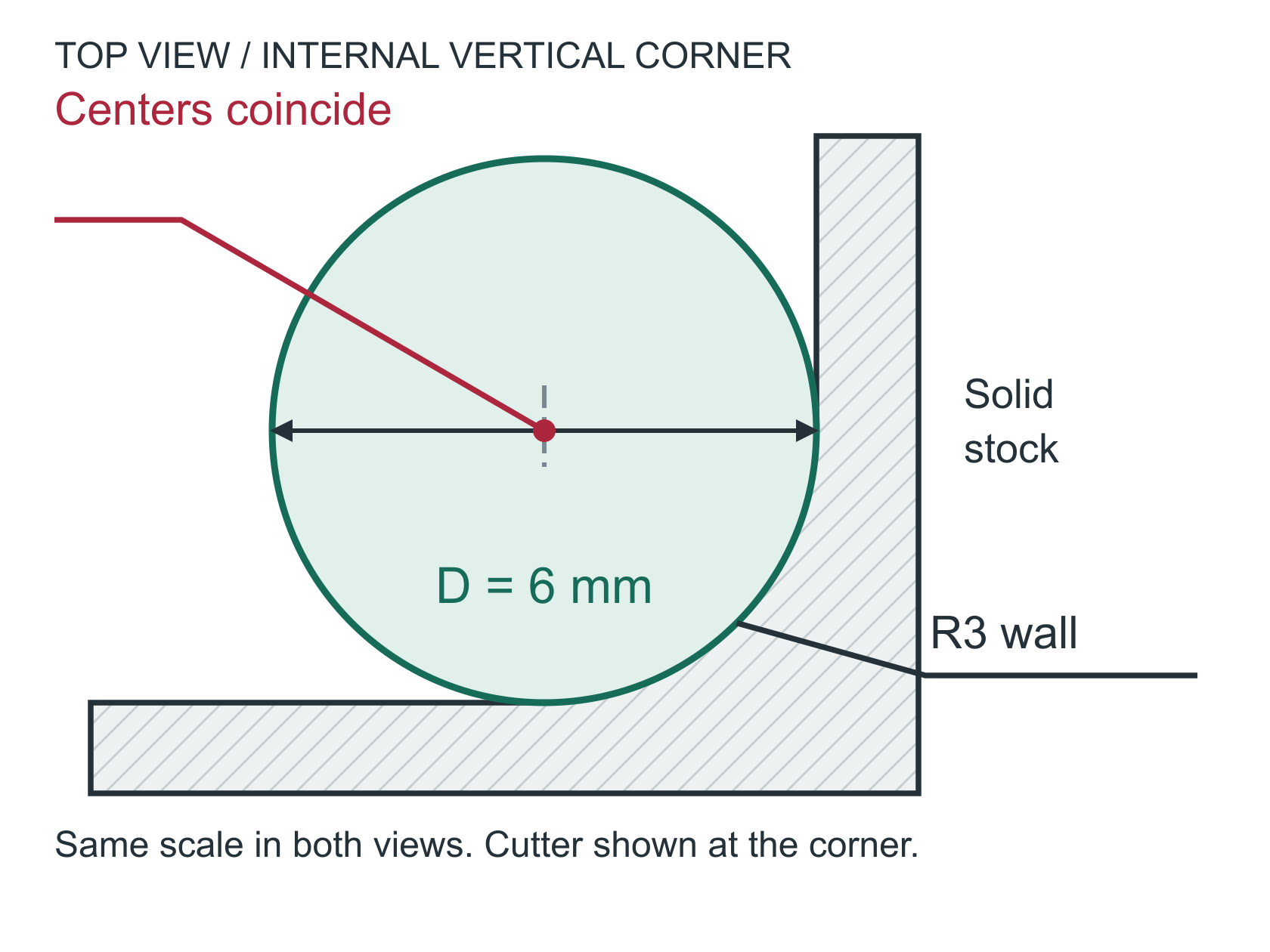
Top view of an R3 inside corner with a radius 3 cutter tangent to both walls. The corner and cutter centers coincide.

R3 corner / diameter 6 cutter

02Larger corner: room to sweep
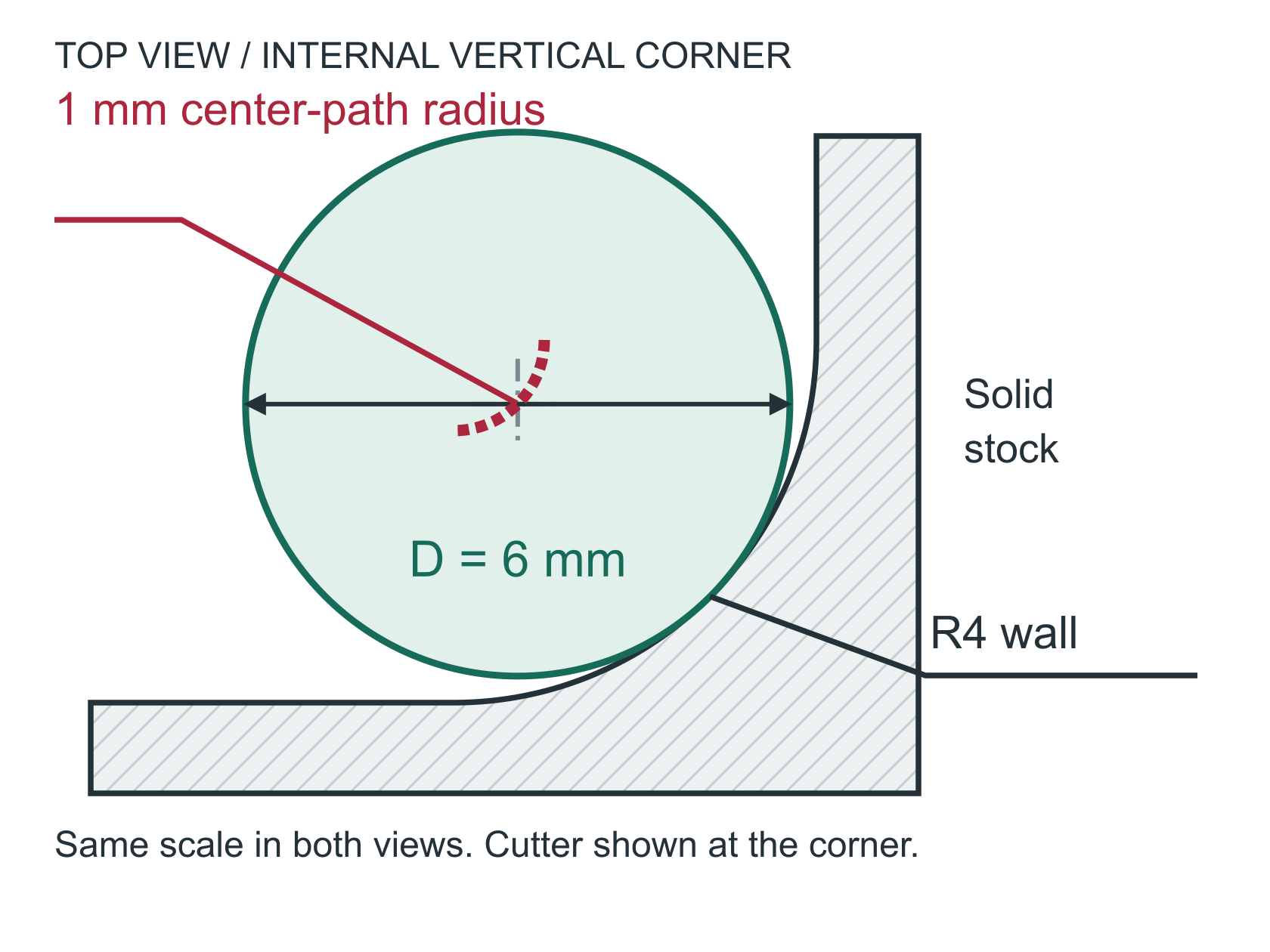
Top view of an R4 corner and a radius 3 cutter. A dashed radius 1 arc traces the cutter center around the corner.

R4 corner / diameter 6 cutter

WORKED EXAMPLE / mm

Corner-path radius = R - D/2

R3: 3 - 6/2 = 0 mm | R4: 4 - 6/2 = 1 mm
03Reduce unnecessary reach

Flutes provide chip space; the neck and holder also need clearance. A deep pocket may require a long, less rigid tool.

CAD: keep nonfunctional pockets shallow.

04Clear square mating corners
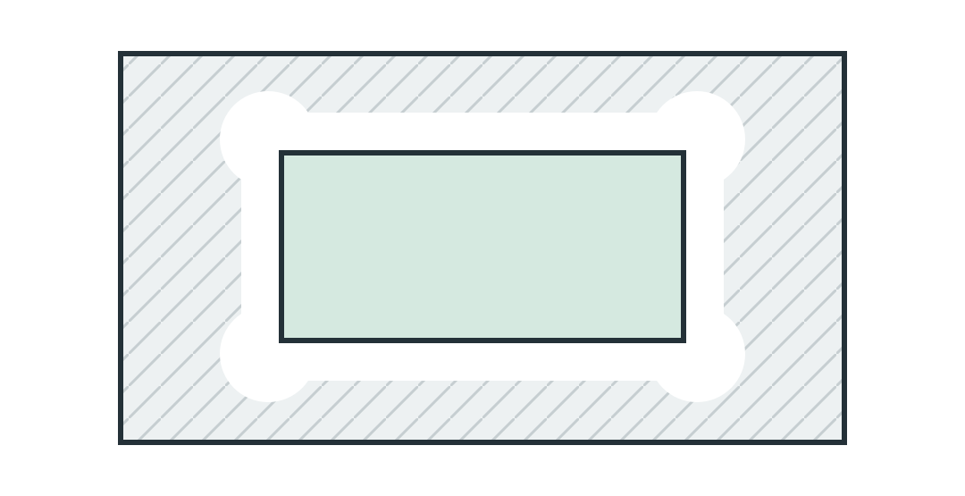
A round tool leaves an inside radius. Local corner relief can clear a square insert; verify fit and the remaining load-bearing section.

CAD: add relief only where permitted.

05Plan the tool approaches
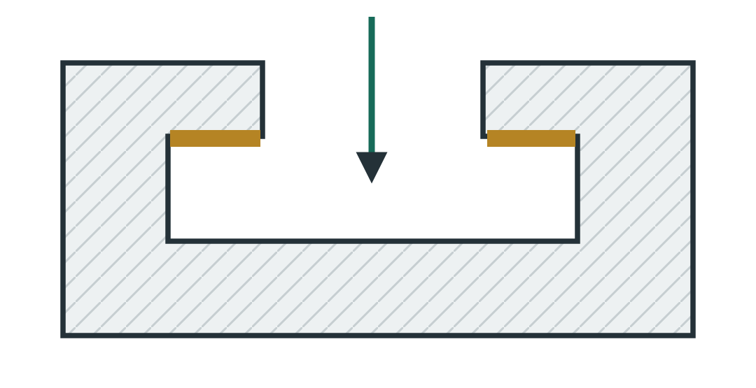
Group accessible features where function permits. Re-clamping adds handling; undercuts still need a tool entry and exit path.

CAD: review access and necessary setups early.

06Distinguish blind and through
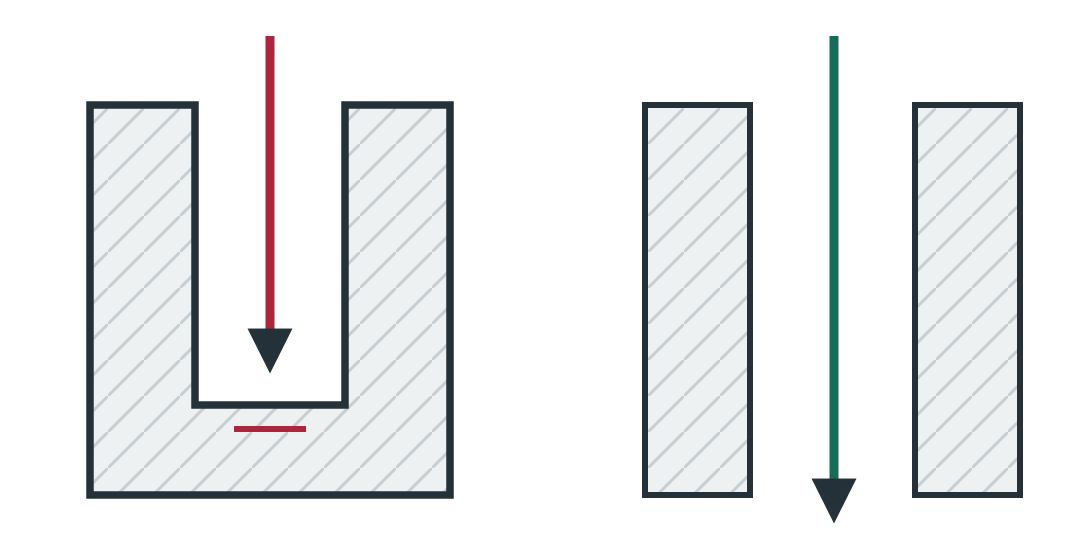
Wire EDM needs a through path in conductive material and wire entry. A blind floor needs another approach, such as sinker EDM.

CAD: preserve required floors and sealing walls.

WHAT THIS DOES NOT PROVE

A larger corner helps the toolpath; it does not prove tool reach. Check flute, neck and holder clearance separately.

BEFORE RELEASE Protect fit, loads, sealing and required material sections when changing geometry.
  • Identify the smallest internal vertical radius.
  • Dimension pocket depth separately from wall height.
  • Check tool and holder access to every feature.
  • Identify square-corner mating requirements.
  • Mark any permitted corner relief on the drawing.
  • Discuss inaccessible undercuts before release.

Illustrative geometry; not to scale. No universal shop limits or structural approval. Drawing and approved process requirements govern.

REV 3 / 2026-09-23 / 1 PAGEdigitalmachine.com/engineering/dfm-guide
More design context & checklist

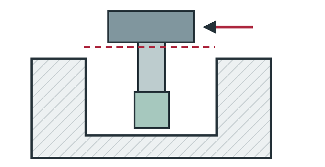
Same 24 mm pocket depth. A 6 mm cutter in an R3 corner has zero radius clearance; R4 gives 1 mm. Depth / cutter diameter remains 4:1 in both cases. This is geometry, not a reach approval. Illustrative geometry, not a production drawing.

Corner clearance
A larger internal vertical radius gives the cutter room to sweep through the corner. Verify the mating part before changing it; a functional sharp corner may need relief or another process.
Reach is not just depth
Check flute length, relieved neck, holder diameter and adjacent walls. A cutter can reach the floor while its holder still collides with the part.
Process boundary
Wire EDM needs an accessible through-cut in conductive material. A blind pocket requires a different approach; do not specify wire EDM simply because a corner is square.

In any alloy, long tools and unsupported walls need joint review. Hardness, tool geometry and cutting conditions change the workable envelope; no universal L/D ratio establishes capability.

Review prompts only; checks are not stored or sent and do not constitute approval.
FIELD GUIDE 02

Holes & blind threads

Separate bore depth, full thread depth and fastener engagement.

Download guide 02 (PDF, 1 page)
DIGITAL MACHINEDESIGN DESK / DFM-02

Holes & blind threads

Separate bore depth, full thread depth and fastener engagement.

DESIGN INTENTUsable thread depth is not drill depth.
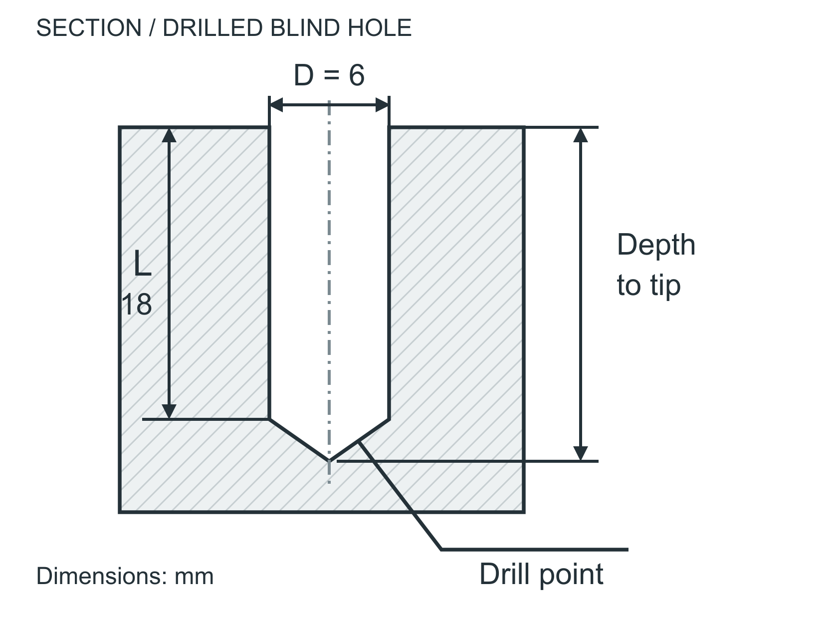
01Drilled hole: define the endpoint
Section of a blind drilled hole. Diameter D is across the clear bore. L runs from the top face to the end of the cylinder; a separate arrow extends to the drill tip.

L stops before the drill point

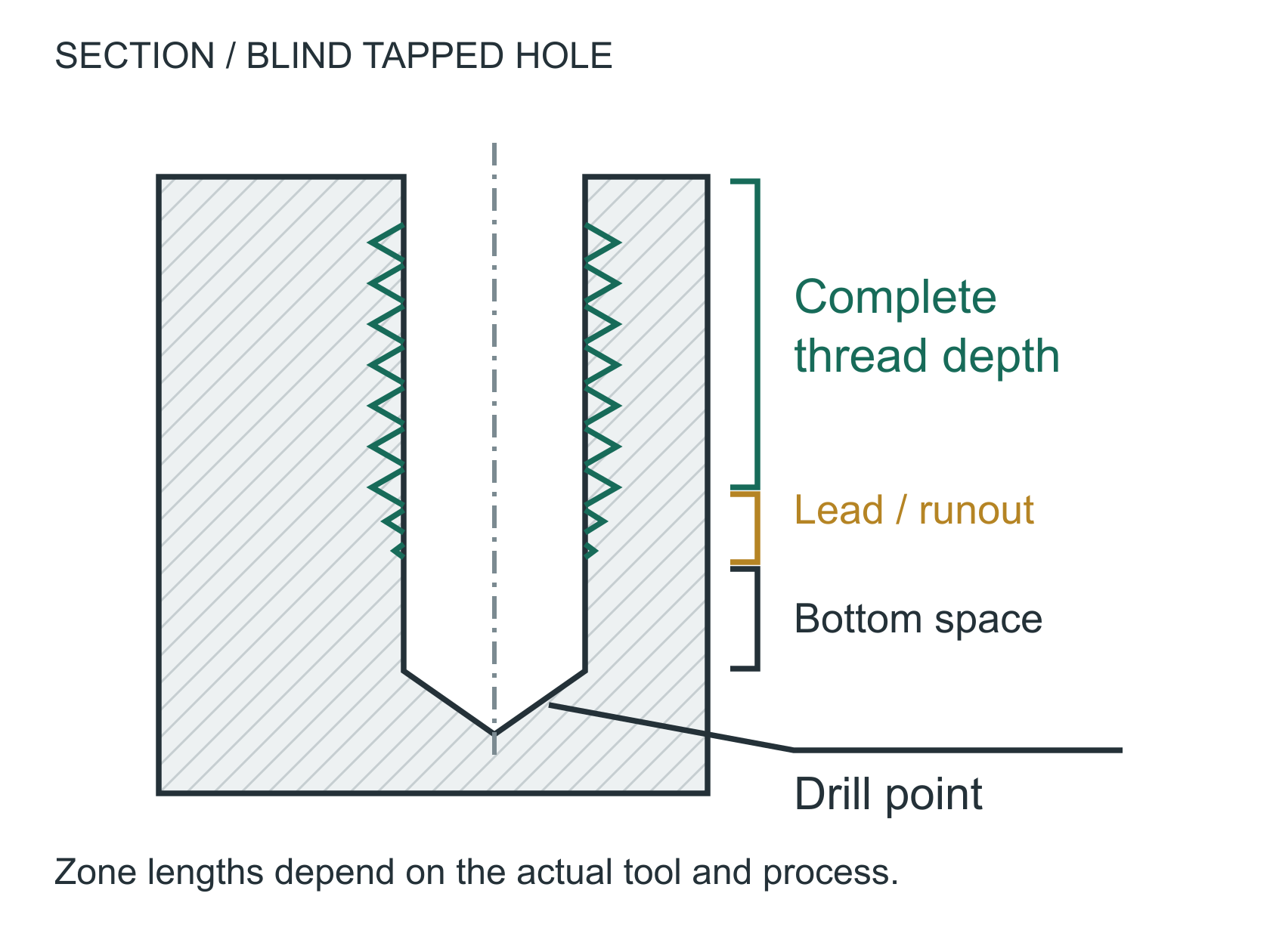
02Blind thread: reserve bottom space
Section of a blind threaded hole showing complete threads, incomplete lead and runout, bottom clearance, and the drill point below. No allowance dimensions are prescribed.

Complete thread first, tool allowance below

WORKED EXAMPLE / mm

Hole ratio = full-diameter depth / bore diameter

18 / 6 = 3:1 | 60 / 6 = 10:1
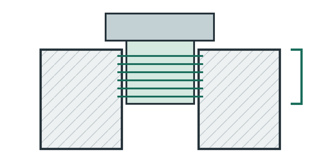
03Check the assembled joint

Engagement is the overlap of mating threads, not drilled depth. Required overlap depends on loads, materials and the fastener.

CAD: check bolt overlap in the assembly.

04Give chips an exit

Blind and through holes need different chip strategies. Tool geometry, coolant and cutting cycle must match the actual hole.

CAD: use through holes where function allows.

05Use available sizes when suitable

Standard drills can simplify tooling. A required fit may still need reaming or boring; nonstandard sizes do not always need interpolation.

CAD: keep the required fit, not an arbitrary size.

06Make passages cleanable

Cross holes can leave burrs inside the part. Include access for deburring, cleaning and verification of critical intersections.

CAD: locate intersections with cleanup in mind.

WHAT THIS DOES NOT PROVE

Specify complete usable thread depth. Set lead, runout and bottom allowance using the selected tool and chip strategy.

BEFORE RELEASE Protect fit, loads, sealing and required material sections when changing geometry.
  • State thread standard, size, pitch and class.
  • Distinguish through holes from blind holes.
  • Dimension required complete thread depth.
  • Confirm actual mating-fastener overlap and loads.
  • Allow tool-specific bottom clearance.
  • Review intersection burrs and cleaning access.

Illustrative geometry; not to scale. No universal shop limits or structural approval. Drawing and approved process requirements govern.

REV 3 / 2026-09-23 / 1 PAGEdigitalmachine.com/engineering/dfm-guide
More design context & checklist

Left: a 6 mm bore with 18 mm full-diameter depth has L/D = 3. A 60 mm depth at the same diameter would be 10. Right: blind-thread zones are schematic, with no universal bottom-clearance dimension. Illustrative geometry, not a production drawing.

Depth callouts
State whether hole depth is to the drill tip or to full diameter. For blind threads, specify complete usable thread depth, not an ambiguous tap depth.
Thread clearance
Keep bolt engagement, complete thread depth, tap lead/runout and drill-point allowance separate. Select bottom clearance from the actual tool and chip strategy, not a fixed extra multiple of diameter.
Process selection
Deep holes require coolant, chip and guidance planning. Select the drilling process from the actual depth, diameter, material and tooling; a depth ratio alone does not mandate gun drilling.

Select cut or form tapping with the tool supplier for the actual alloy and condition. Form taps displace material and need the specified pre-hole size. A cut-tap drill table is not a form-tap table.

Review prompts only; checks are not stored or sent and do not constitute approval.
FIELD GUIDE 03

Thin walls & material behavior

Review the whole wall: height, thickness, support and material condition.

Download guide 03 (PDF, 1 page)
DIGITAL MACHINEDESIGN DESK / DFM-03

Thin walls & material behavior

Review the whole wall: height, thickness, support and material condition.

DESIGN INTENTDimension wall height and thickness together.
01Tall, slender section
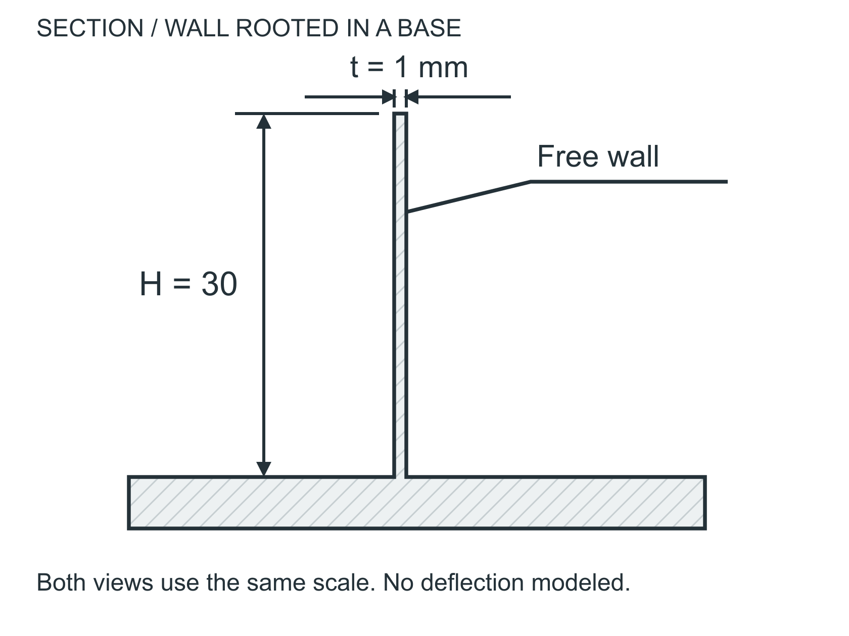
Section of a 30 mm high, 1 mm thick wall rooted in a base. Height H is measured above the base and thickness t across the wall.

H = 30 mm / t = 1 mm

02Shorter, thicker section
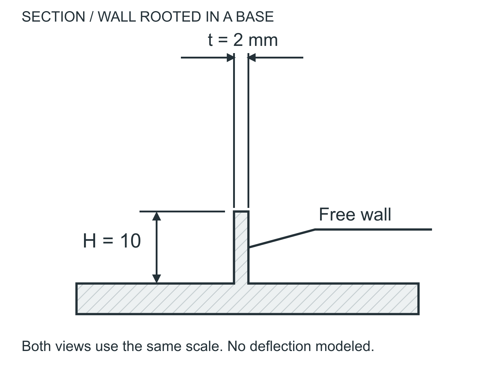
Same-scale section of a 10 mm high, 2 mm thick wall rooted in a base. Both height and thickness are dimensioned.

H = 10 mm / t = 2 mm

WORKED EXAMPLE / mm

Geometry ratio = unsupported height / thickness

30 / 1 = 30 | 10 / 2 = 5
03Support the free span

A rib or thicker root can help support a wall. Preserve clearance and mass targets; check loads, fatigue and stress concentrations.

CAD: shorten spans or add a permitted rib.

04Provide a stable grip

Thin features can move under clamp force and spring back when released. A supported gripping area helps the workholding plan.

CAD: leave accessible support and grip faces.

05Avoid needless one-sided cuts

Residual stress and asymmetric removal can move the part. Review stock condition and the roughing/finishing sequence with the shop.

CAD: remove only the material function needs.

06Specify the material state

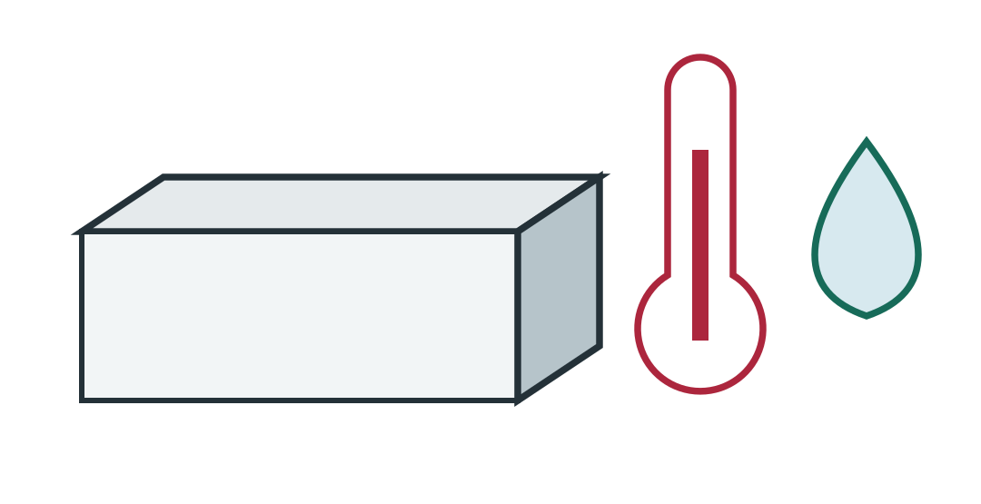
Alloy/temper and polymer grade matter. Temperature, moisture and stress relaxation can change dimensions after machining.

CAD: define grade and measurement condition.

WHAT THIS DOES NOT PROVE

H/t describes slenderness. It is not a stiffness calculation, a vibration prediction or a universal pass/fail limit.

BEFORE RELEASE Protect fit, loads, sealing and required material sections when changing geometry.
  • Dimension height and thickness together.
  • Show where supports or ribs are permitted.
  • Identify critical free-state dimensions.
  • Specify alloy, temper/hardness or polymer grade.
  • Review stock stress and asymmetric removal.
  • Agree measurement temperature and conditioning when relevant.

Illustrative geometry; not to scale. No universal shop limits or structural approval. Drawing and approved process requirements govern.

REV 3 / 2026-09-23 / 1 PAGEdigitalmachine.com/engineering/dfm-guide
More design context & checklist

A 30 mm high, 1 mm thick wall has H/t = 30. A 10 mm high, 2 mm thick wall has H/t = 5. These ratios describe geometry only; they are not pass/fail criteria or a calculated deflection. Illustrative geometry, not a production drawing.

Support the feature
Consider a shorter unsupported span, a thicker wall or an allowed rib. Preserve required clearance and mass targets. Clamping access belongs in the review before stock removal.
Separate material families
A nominal thickness does not transfer unchanged between aluminum, stainless and plastics. Review alloy, temper or hardness, remaining section and stock condition.
Plastics need conditioning
Heat, moisture and stress relaxation can change dimensions. Specify measurement conditions where they matter, and review coolant compatibility and clamping pressure.

For PEEK, acetal, nylon and filled polymers, identify the exact grade and conditioning requirements. Filled grades can be abrasive; nylon moisture uptake can affect size. Do not treat all plastics as one material.

Review prompts only; checks are not stored or sent and do not constitute approval.
FIELD GUIDE 04

Tolerances & datums

Define the functional relationship, then agree how it will be made and measured.

Download guide 04 (PDF, 1 page)
DIGITAL MACHINEDESIGN DESK / DFM-04

Tolerances & datums

Define the functional relationship, then agree how it will be made and measured.

DESIGN INTENTControl the span that the assembly actually needs.
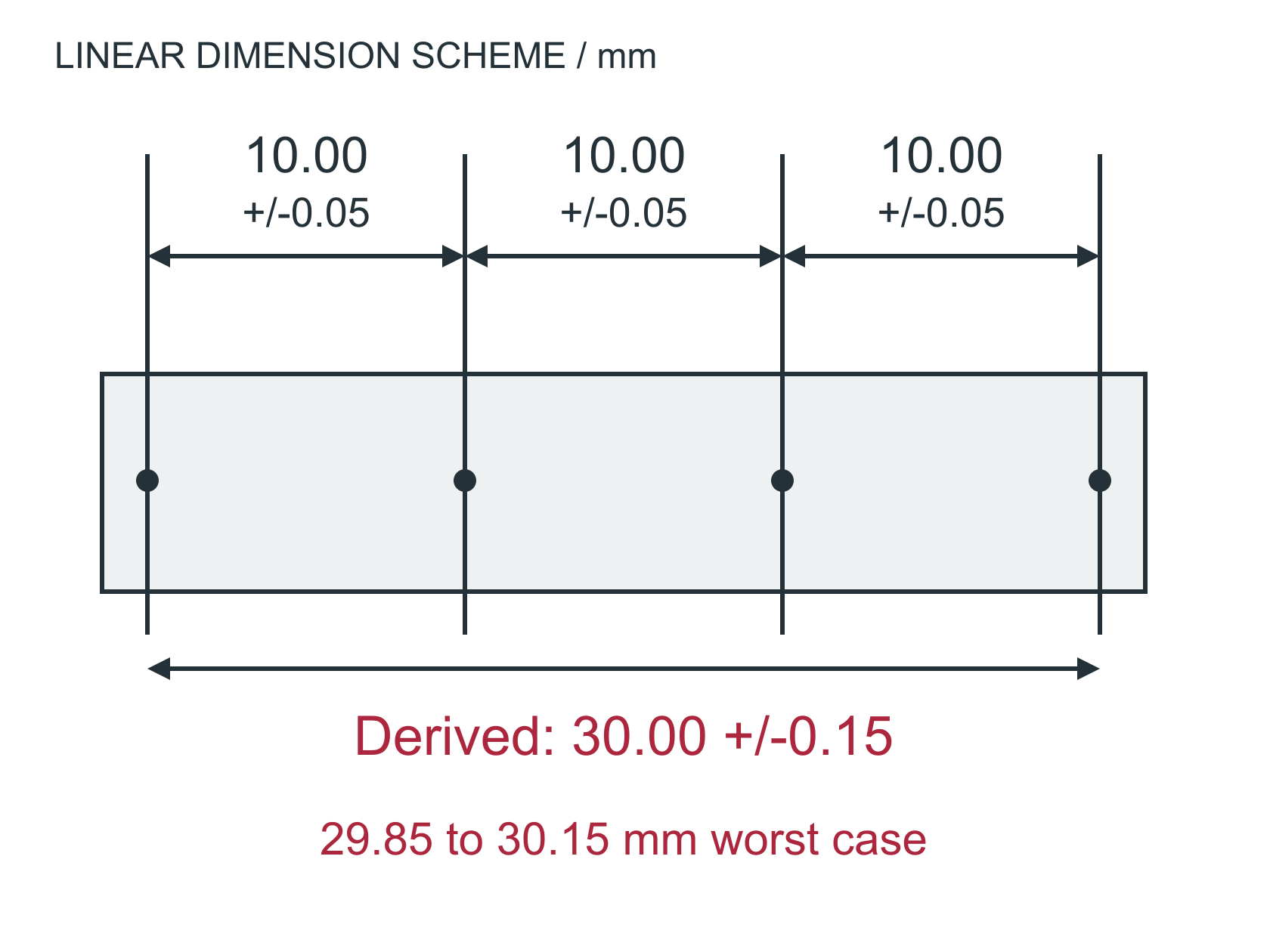
01Three toleranced segments
Four feature lines with three chained 10.00 plus or minus 0.05 mm dimensions. The overall span is derived as 30.00 plus or minus 0.15 mm.

Worst-case overall variation: +/-0.15 mm

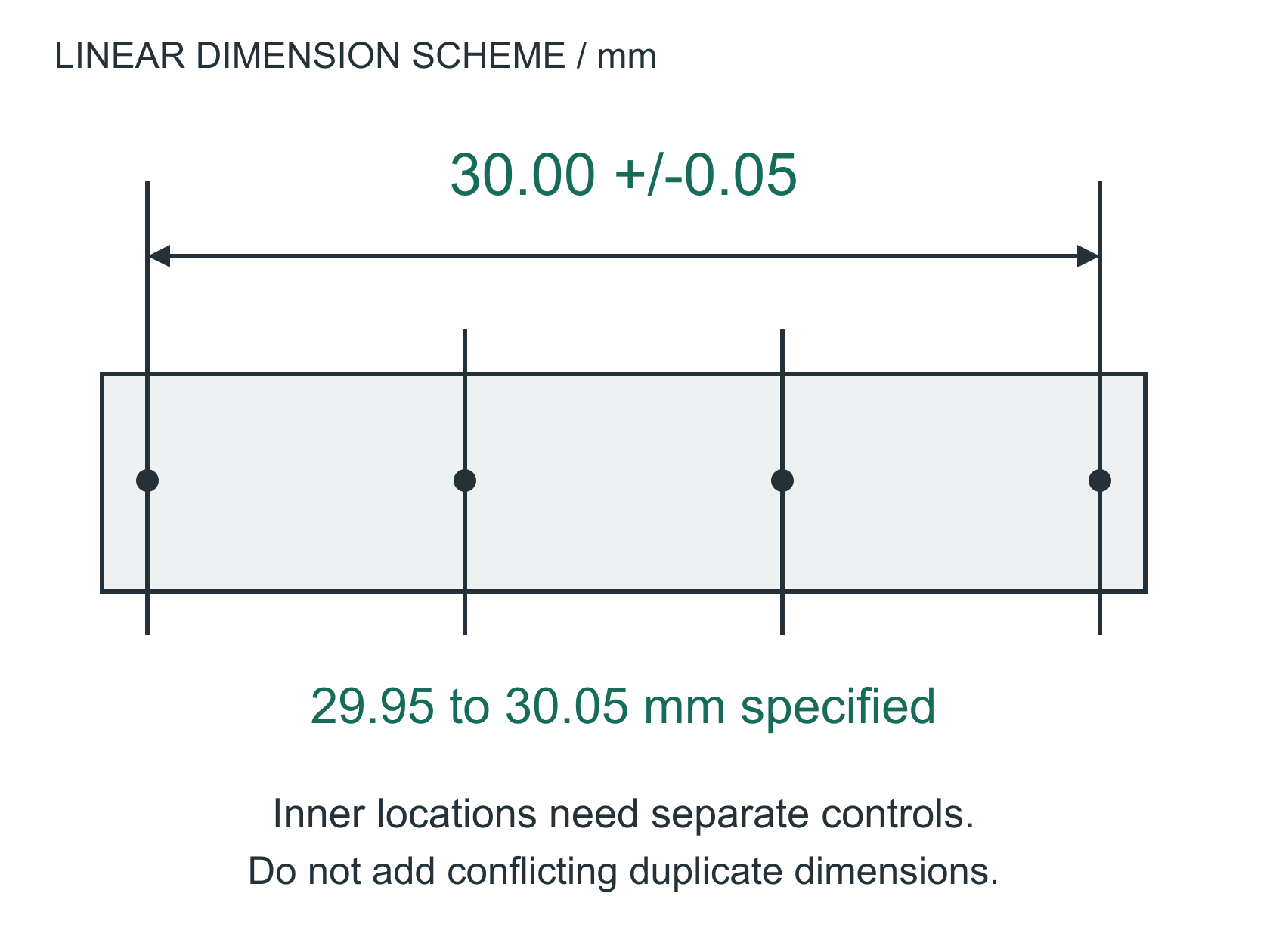
02One functional span
The same four feature lines with only the overall 30.00 plus or minus 0.05 mm span directly controlled. Inner locations are not defined by this dimension.

Specified overall variation: +/-0.05 mm

WORKED EXAMPLE / mm

Worst-case chain: add absolute tolerance contributions

0.05 + 0.05 + 0.05 = +/-0.15 mm on the sum
03Choose assembly references

Datums are references for controlling geometry. Start with how the part seats, locates and clocks in its assembly.

CAD: select accessible functional datum features.

04Make the feature measurable

A probe or gauge needs access. Discuss critical features and inspection fixturing early; a tolerance needs a suitable measurement method.

CAD: leave access to the controlled feature.

05Put precision where it matters

Identify sealing, sliding, bearing and alignment interfaces. Blanket tight tolerances add work without necessarily helping function.

CAD: apply tight controls locally where needed.

06Define when size must be met

Coating, heat treatment and temperature can change size or form. The inspection condition belongs in the definition of the part.

CAD: state pre-process versus final dimensions.

WHAT THIS DOES NOT PROVE

Changing the dimension layout does not improve the process. The tighter direct span is a new requirement to manufacture and inspect.

BEFORE RELEASE Protect fit, loads, sealing and required material sections when changing geometry.
  • Identify function-critical interfaces.
  • Check the complete tolerance stack.
  • Define and order required datum references.
  • Avoid conflicting duplicate dimensions.
  • Confirm access for the proposed inspection method.
  • State final condition and applicable standard.
More design context & checklist

Three independent 10.00 +/-0.05 mm lengths sum to 30.00 +/-0.15 mm worst case. A directly controlled 30.00 +/-0.05 mm span is a different requirement, not an automatic benefit of changing the dimension layout. Illustrative geometry, not a production drawing.

Start with the interface
Identify which faces locate, which holes fasten, and which surfaces seal. Apply tighter controls where the function requires them; do not relax a functional tolerance just to simplify machining.
Datums and inspection
Choose datum features that represent the assembly. Review their physical accessibility for fixturing and measurement without redefining the design intent around a convenient setup.
State the convention
Identify the governing drawing standard and edition. ASME Y14.5 defines dimensioning and tolerancing practice; it does not prescribe universal CNC wall thicknesses or cost multipliers.

Thermal expansion, coating buildup and heat-treatment distortion can affect final acceptance. State the required inspection condition and whether dimensions apply before or after outside processing.

Review prompts only; checks are not stored or sent and do not constitute approval.
FIELD GUIDE 05

Surface finish & coatings

Treat texture, appearance and coating requirements as separate decisions.

Download guide 05 (PDF, 1 page)
DIGITAL MACHINEDESIGN DESK / DFM-05

Surface finish & coatings

Treat texture, appearance and coating requirements as separate decisions.

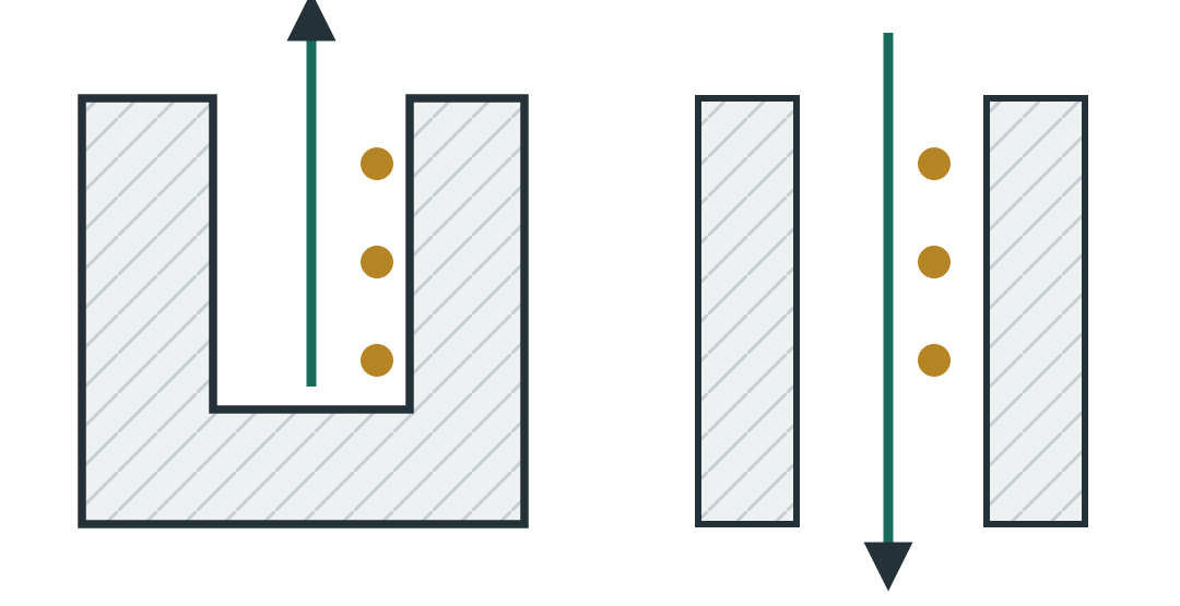
DESIGN INTENTDeposits shrink bores and grow outside diameters.
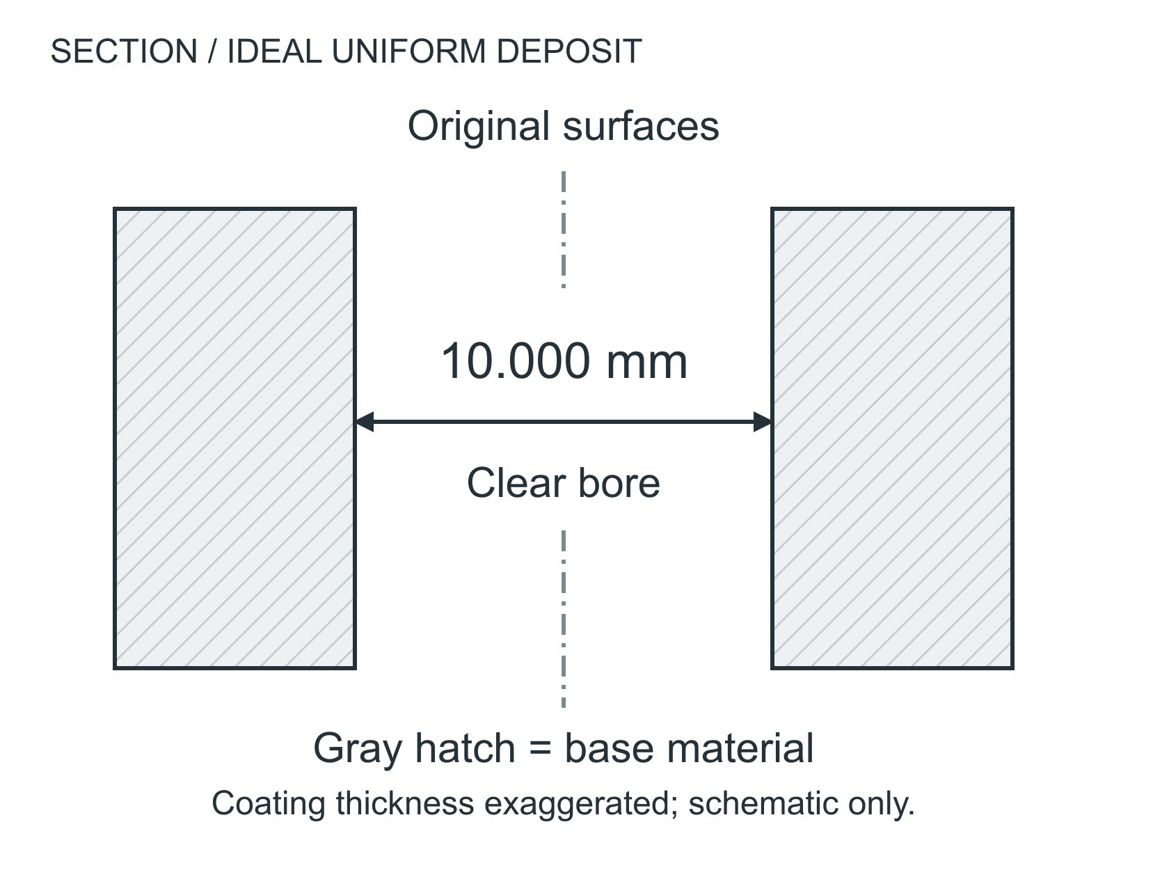
01Before: machined bore
Section through a bore with gray substrate on both sides. An arrow across the open space measures the initial 10.000 mm diameter.

Initial diameter = 10.000 mm

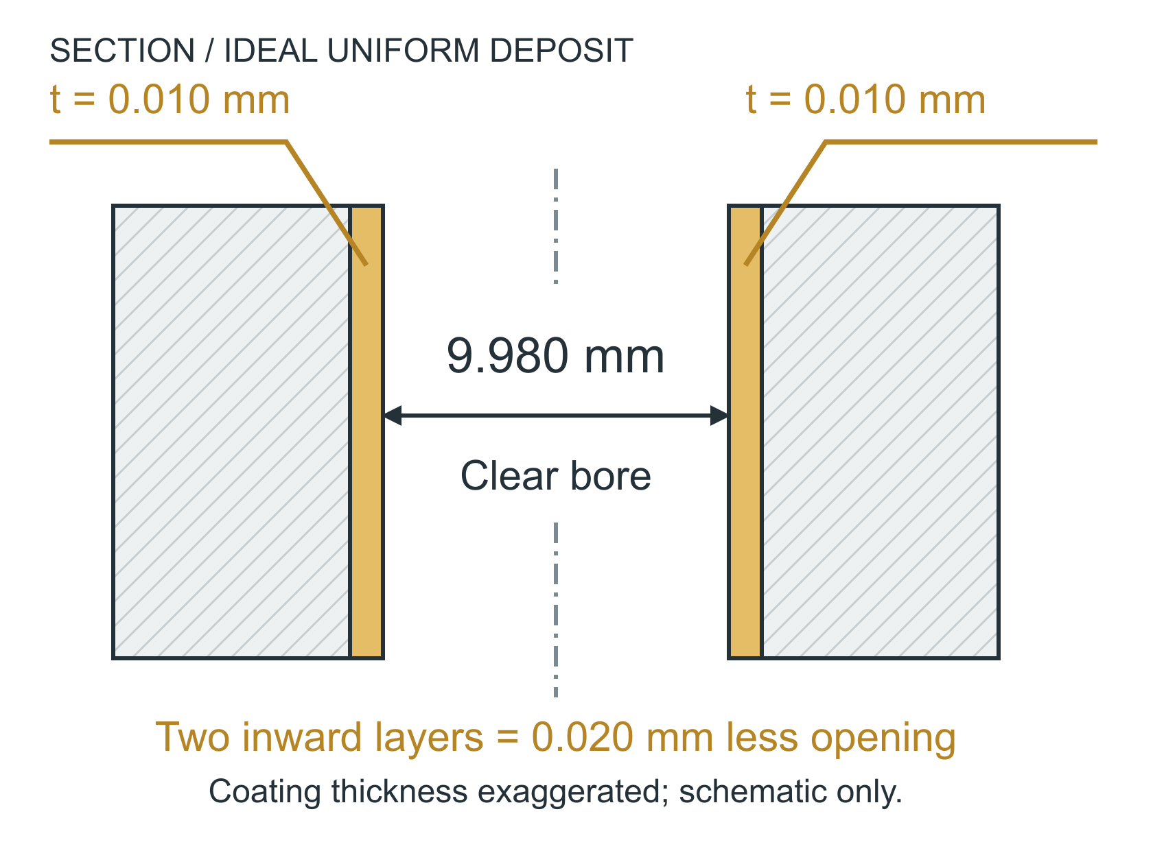
02After: inward deposit on both walls
The same bore after an ideal uniform deposit. Gold layers project into the opening from both walls. The finished opening is 9.980 mm, reduced by 0.020 mm total.

Finished diameter = 9.980 mm

WORKED EXAMPLE / mm

Bore: Dfinal = Dinitial - 2t | Outside diameter: + 2t

10.000 - (2 x 0.010) = 9.980 mm
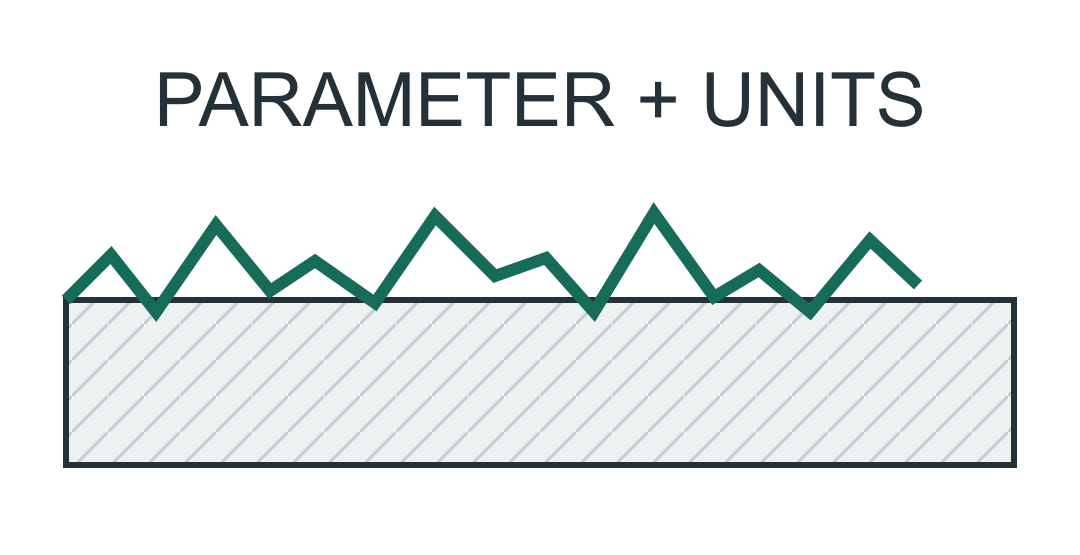
03Separate texture from looks

A process name or cosmetic sample is not a roughness value. State parameter and units where texture affects function.

CAD: mark functional and cosmetic zones.

04Show what stays uncoated

Masking keeps selected surfaces free of a coating. Identify critical bores, threads, contacts and datum features; define mask boundaries.

CAD: mark no-coat and contact-restriction zones.

05Review edges and recesses

Local buildup depends on geometry and process access. The uniform 2t example does not predict coating distribution.

CAD: agree actual allowance before sizing fits.

06Define the complete finish

State process specification/revision, required records and final size. Digital Machine coordinates outside special processes; color is not equivalence.

CAD: call out the finish and acceptance condition.

WHAT THIS DOES NOT PROVE

Here t is buildup beyond the original surface, not automatically total coating thickness. Anodizing also penetrates the substrate; use process-specific growth data.

BEFORE RELEASE Protect fit, loads, sealing and required material sections when changing geometry.
  • Separate cosmetic zones from functional surfaces.
  • State roughness parameter and units.
  • Specify coating type and governing revision.
  • Identify masking and rack/contact restrictions.
  • State pre- or post-finish dimensional acceptance.
  • Request required process certificates and inspection records.

Illustrative geometry; not to scale. No universal shop limits or structural approval. Drawing and approved process requirements govern.

REV 3 / 2026-09-23 / 1 PAGEdigitalmachine.com/engineering/dfm-guide
More design context & checklist

For an ideal uniform inward deposit of 0.010 mm per side, a 10.000 mm bore becomes 9.980 mm: finished diameter = initial diameter - 2t. This does not model anodizing penetration, uneven buildup or a particular coating process. Illustrative geometry, not a production drawing.

Local finish requirements
Identify the sealing, sliding or bearing surface that needs controlled texture. Include the roughness parameter and units; a cosmetic sample is not a numerical roughness requirement.
Masking and buildup
Identify bores, threads, electrical contacts and datum features that must be masked or controlled after coating. Agree allowances with the finishing supplier.
Outside processing
At Digital Machine, anodizing, plating, passivation and heat treatment are coordinated with outside partners. Required process documentation and final inspection belong in the purchase requirements.

Do not substitute a finish solely by appearance. Confirm substrate compatibility, environment, electrical needs, wear, cleanliness and the governing specification before approving a change.

Review prompts only; checks are not stored or sent and do not constitute approval.
FIELD GUIDE 06

Drawing release checklist

Make the model, drawing and purchase requirements tell the same story.

Download guide 06 (PDF, 1 page)
DIGITAL MACHINEDESIGN DESK / DFM-06

Drawing release checklist

Make the model, drawing and purchase requirements tell the same story.

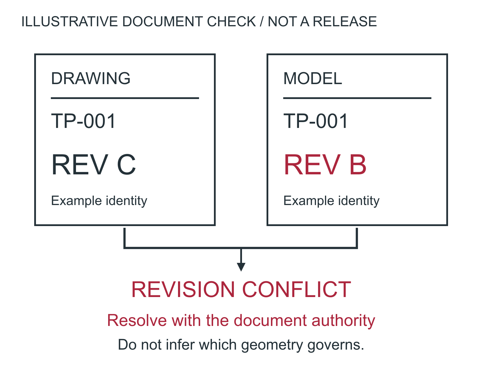
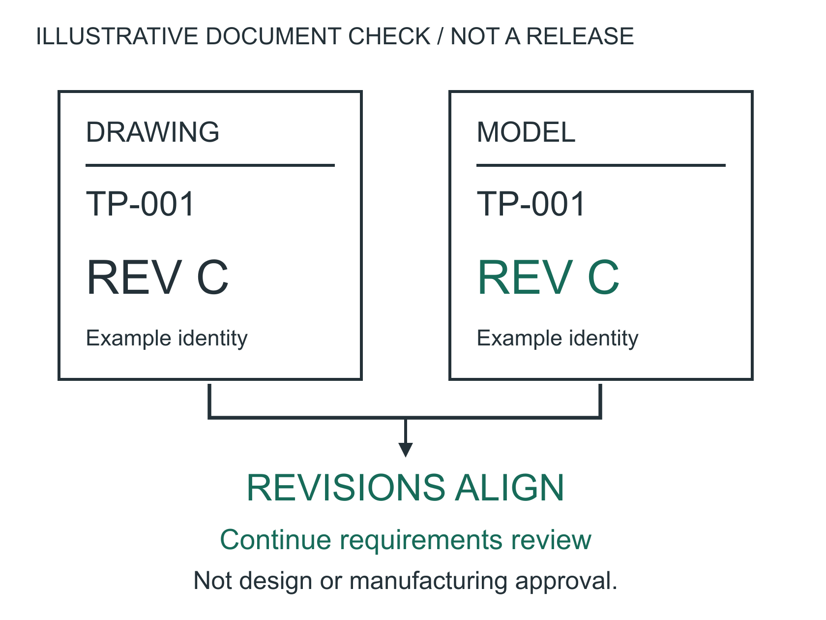
DESIGN INTENTMatching revisions are a check, not release approval.
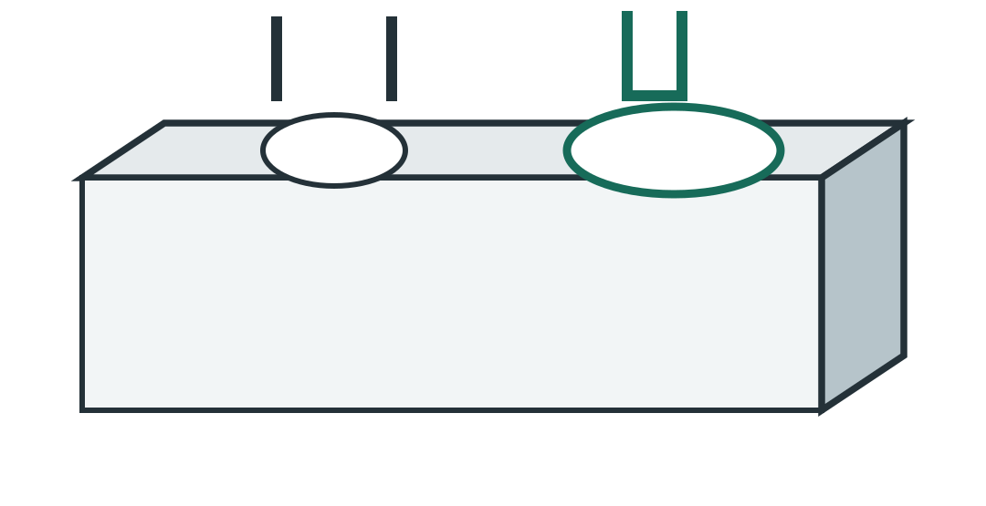
01Conflict: stop and resolve
Drawing revision C and model revision B for the same illustrative part TP-001, connected by a mismatch warning.

Example part TP-001 / drawing C / model B

02Aligned: continue the review
Drawing revision C and model revision C for example part TP-001. Revision alignment leads to further requirement checks, not an approval stamp.

Example part TP-001 / drawing C / model C

WORKED EXAMPLE / DOCUMENT CONTROL

Release gate: identity + revision + requirements + authority

Matching letters alone do not resolve conflicting geometry.
03Identity, units & precedence

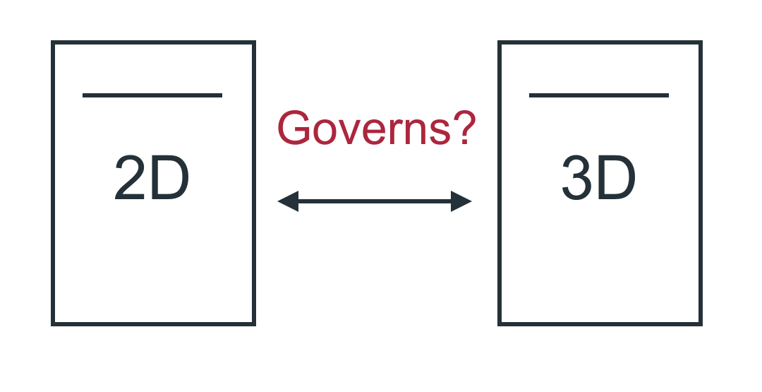
State part number, units, revision and what governs if the drawing and model conflict. Different revision codes may be intentional.

Resolve the controlled document relationship.

04Material & process definition

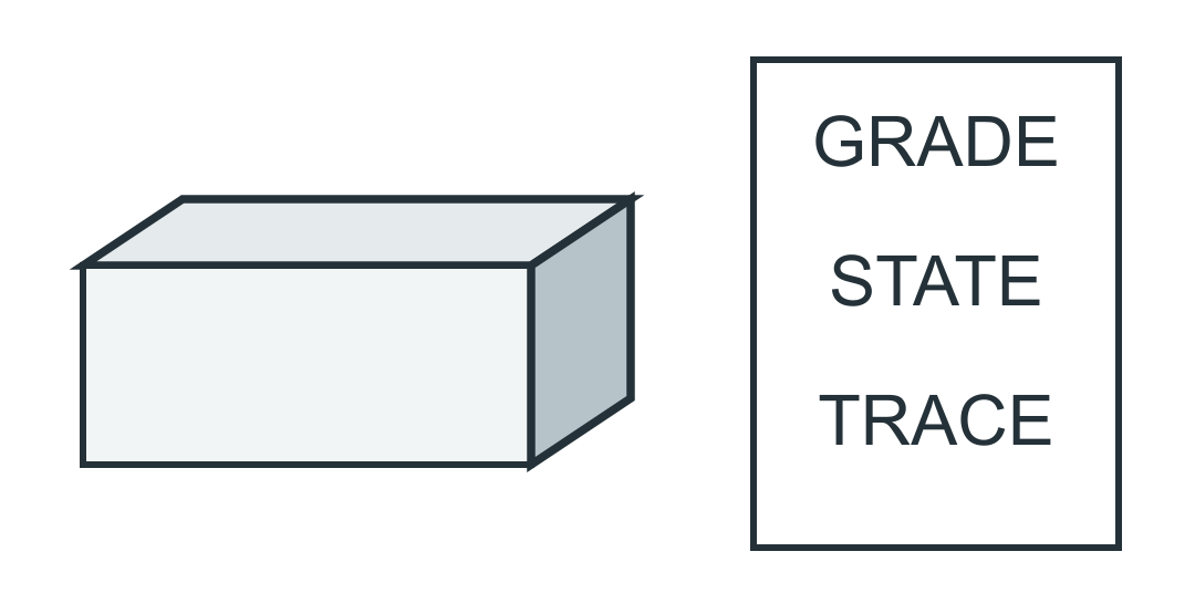
Specify grade, condition, approved alternatives and special processes. Include masking, cleanliness and packaging where required.

Do not authorize a substitution by omission.

05Inspection & delivery records

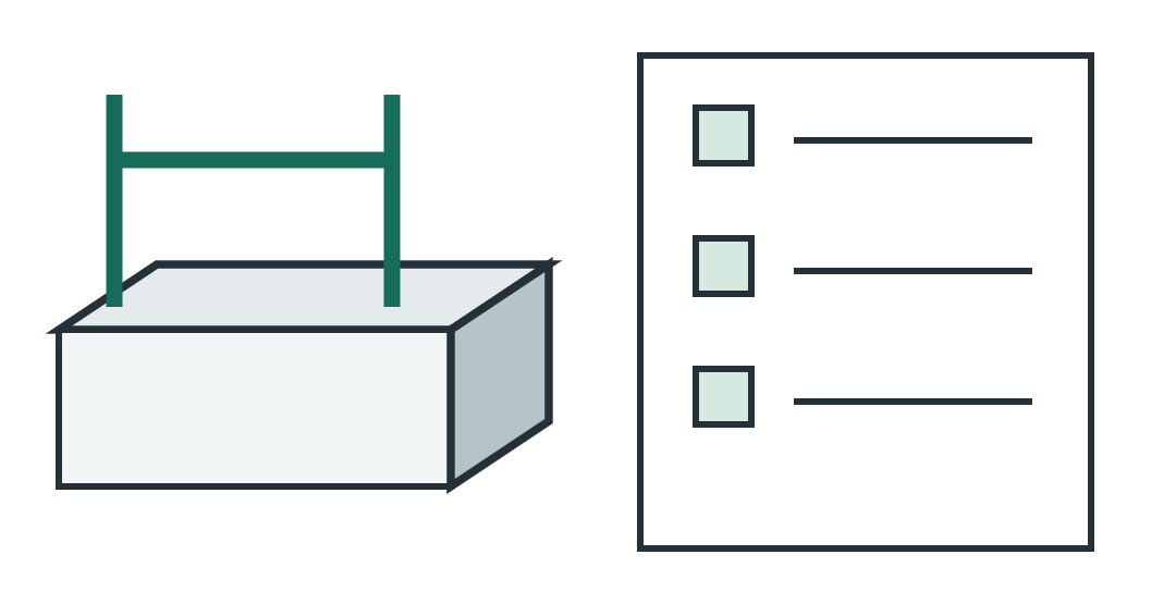
Identify critical features, acceptance condition and required inspection or process certificates in the purchase requirements.

Specify deliverables before production starts.

06Approved, secure handoff

Resolve deviations with the responsible authority. Arrange secure transfer before sending controlled drawings or models.

Never put controlled technical data in public forms.

WHAT THIS DOES NOT PROVE

Follow the document relationship defined by the customer. Different model and drawing revision codes can be intentional if explicitly controlled.

BEFORE RELEASE Protect fit, loads, sealing and required material sections when changing geometry.
  • Match part number and revision across all files.
  • Confirm units, scale and document precedence.
  • State material grade and required condition.
  • Resolve critical dimensions, threads and datums.
  • Specify finish, masking and outside-process records.
  • Confirm inspection, cleanliness and packaging needs.
  • List approved deviations and who authorized them.
  • Arrange secure transfer before sharing controlled data.
More design context & checklist

A revision mismatch is a release question, not a machining decision. Confirm the authoritative model and drawing revisions before resolving geometry differences. The C/B example is illustrative, not a customer record. Illustrative geometry, not a production drawing.

One definition of the part
State units, part number, revision and model/drawing precedence. Resolve missing dimensions and contradictory notes before release.
Production requirements
Include quantity, material condition, special processes, inspection deliverables and packaging or cleanliness requirements. Identify approved alternatives rather than assuming the shop can substitute them.
Secure handoff
Do not put controlled drawings, models or technical data into public forms. Contact Digital Machine first to arrange an approved secure transfer route.

This worksheet records review questions. Checking every box does not approve manufacturability, validate a design, certify a process or replace customer engineering and quality acceptance.

Review prompts only; checks are not stored or sent and do not constitute approval.
Keep at the design desk

Design guidelines

Six design guides plus two process-planning sheets, each on one page. Updated 2026-09-23. Reference guidance, not an approved process specification or structural validation.

01Pockets & tool access
02Holes & blind threads
03Thin walls & material behavior
04Tolerances & datums
05Surface finish & coatings
06Drawing release checklist
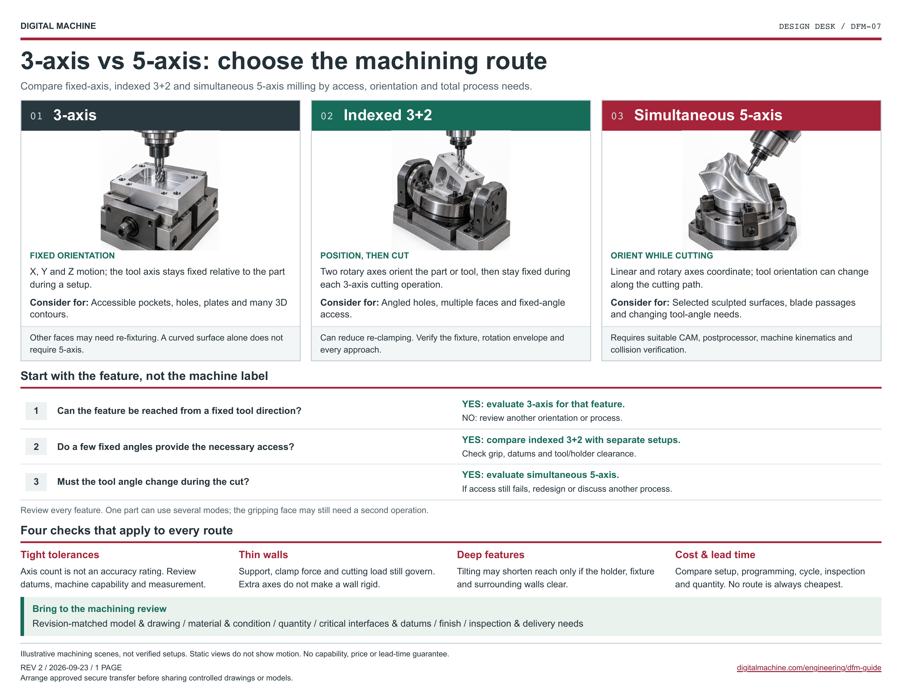
073-axis vs 5-axis: choose the machining route
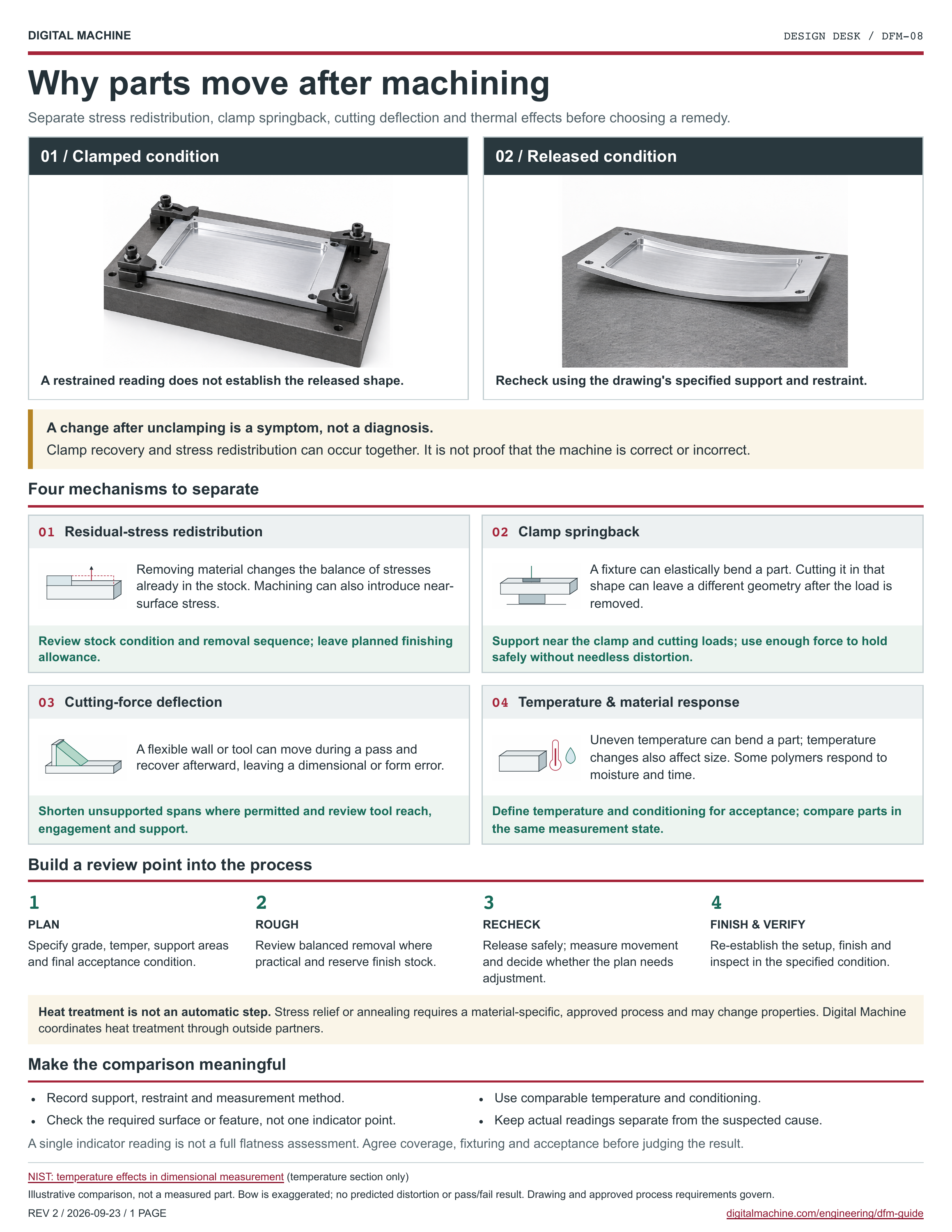
08Why parts move after machining

Process planning

Machining route & part stability

3-axis vs 5-axis: choose the machining route

Compare fixed-axis, indexed 3+2 and simultaneous 5-axis milling by access, orientation and total process needs.

3-axis vs 5-axis: choose the machining route: illustrated one-page sheet

Why parts move after machining

Separate stress redistribution, clamp springback, cutting deflection and thermal effects before choosing a remedy.

Why parts move after machining: illustrated one-page sheet

Practical machining guidelines

Geometry, reach & clearance

These are starting points, not ASME or ISO requirements. Confirm material, geometry, tooling and the governing drawing before manufacture.

Wall thickness
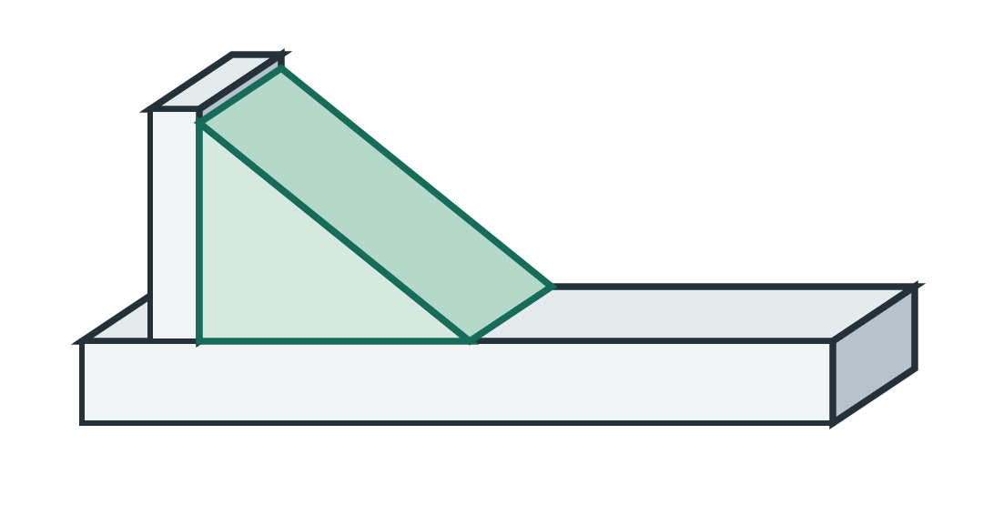
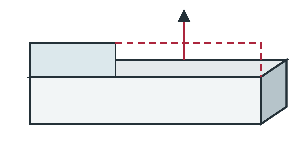
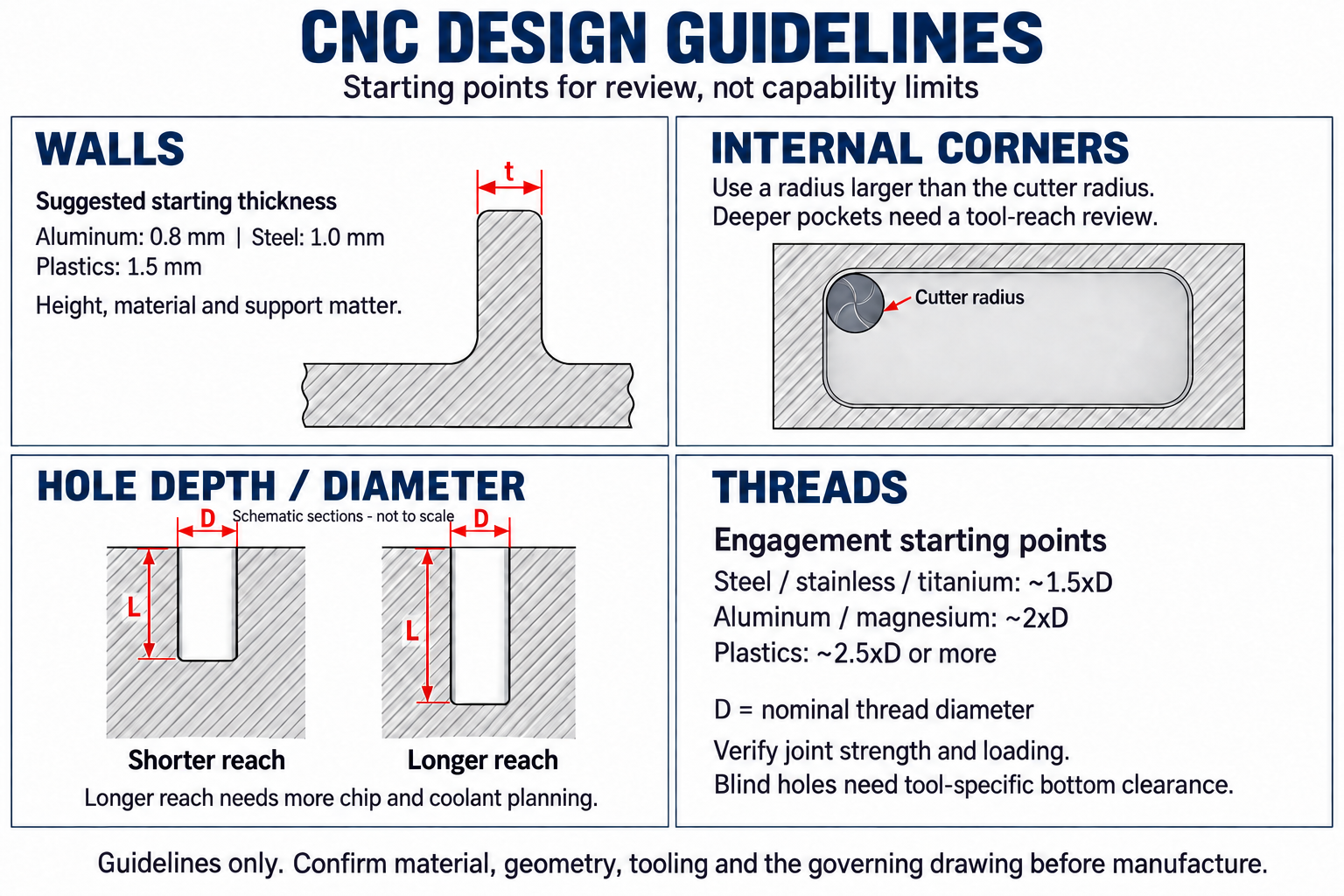
Suggested starting thickness: aluminum 0.8 mm, steel 1.0 mm, plastics 1.5 mm. Wall height, material condition and support matter; thickness alone does not establish stiffness or manufacturability.
Internal corners & tool reach
Use a corner radius larger than the cutter radius. Around 1.3 times the cutter radius is a useful starting point, not a limit. Deeper pockets need a reach review: tool deflection increases rapidly with unsupported length. Corner relief may avoid an additional process. Wire EDM needs through access; a blind pocket may need a different approach, such as sinker EDM.
Hole depth / diameter
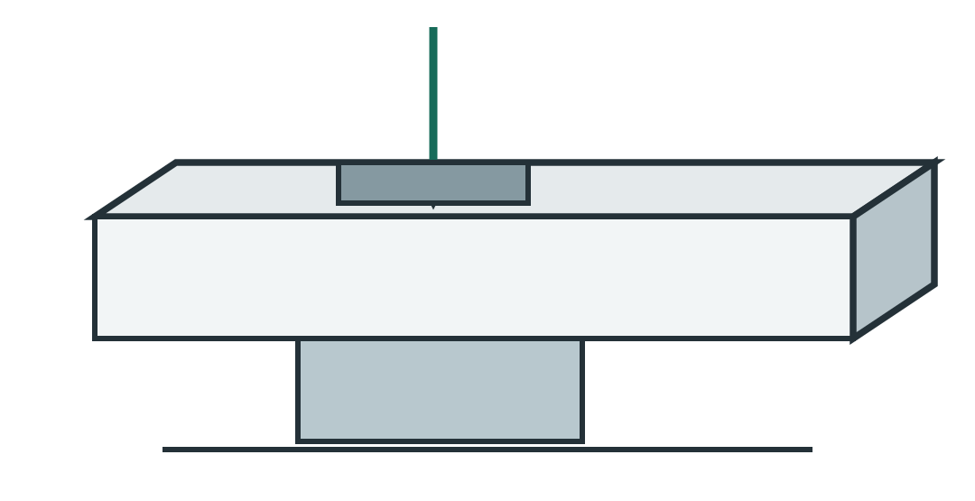
D measures the clear bore, not the surrounding wall. L measures cylindrical bore depth; a drill point adds further depth. For equal diameters, the longer bore has the higher L:D ratio and needs more chip evacuation, coolant and tooling planning. Deep-hole drills or gun drilling may be appropriate; the ratio alone does not select the process.
Threads & blind-hole clearance
Engagement starting points: about 1.5×D for steel, stainless or titanium; 2×D for aluminum or magnesium; 2.5×D or more for plastics. Here D is nominal thread diameter. Verify joint strength and loading. Engagement is the mating thread overlap, not tap travel or drill depth. Blind holes need clearance based on the actual tap lead, thread runout, chip space and drill point.

Interactive Visualizer

DFM geometry review

Review flags identify selected features that deserve closer attention. They are not a cost estimate, a process plan or a manufacturability approval. Material, wall height, tool access and actual cutting conditions still need review.

DFM Parameters

Selected features

Review flags

05
0 / 5feature groups flagged
Baseline geometry

Confirm the full drawing and material.

No additional flags from these selections. Tool access, loading, material and inspection requirements still need review.

Process selection requires the complete geometry and material.

Live Machining Geometry Simulator
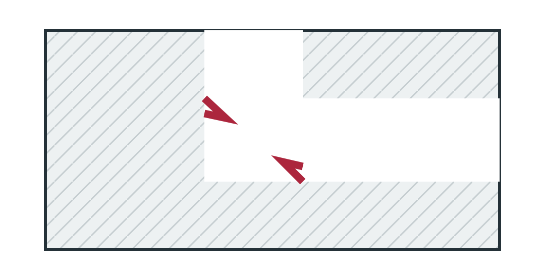
Wall SeparatorTOOLMilled PocketDrilled Hole

Schematic only, not to scale. Red marks indicate review points, not predicted vibration or tool failure.

Selected geometryWall: 2.0 mm; corner R: 3.0 mm; hole L:D: 3:1.

01 · Wall thickness

Thickness is only one dimension.

About 0.8 mm for aluminum and 1.0 mm for steel are useful starting thicknesses, not guaranteed stable limits. Thinner or taller walls need a review of tool pressure, clamping and possible support features.

01

Thin walls, ribs & webs

  • chatter
  • deflection
  • clamping forces
MaterialPlanning exampleHigher-review exampleNotes
Aluminum 60610.8 mm (0.032″)0.5 mm (0.020″)Check temper, stock stress and unsupported height
Stainless 316L1.0 mm (0.040″)0.7 mm (0.028″)Springs back; chatter risk on thin walls
Steel (4140 / 1018)1.0 mm (0.040″)0.7 mm (0.028″)Stable, but watch heat-induced warp
Ti-6Al-4V1.5 mm (0.060″)1.0 mm (0.040″)Review heat, tool pressure and support
Inconel 7181.5 mm (0.060″)1.0 mm (0.040″)Work-hardens fast on thin walls
Plastics (PEEK, Delrin)1.5 mm (0.060″)1.0 mm (0.040″)Flex prevents deeper cuts; need gentle fixturing

These thicknesses are illustrative review starting points, not validated material-specific limits or a published shop capability table. Wall aspect ratio matters too: a 0.8 mm wall that is 50 mm tall is harder to hold than the same wall 5 mm tall. Increasing height-to-thickness ratio warrants a workholding review; none of these thicknesses is an absolute capability limit.

02 · Holes & depth ratio

L:D drives drilling cost.

Hole depth-to-diameter (L:D) ratio helps guide tooling selection. Around 3:1 is often straightforward; longer holes need more attention to chip evacuation, coolant and tool guidance. Beyond 10:1, suitable deep-hole drills or gun drilling may be considered. Pecking is tool-dependent, not a universal requirement.

Drilling a passage from both faces can reduce reach, but the meeting point, bore alignment, steps and burrs must meet the drawing. It is not interchangeable with drilling from one side without a feature-specific review.

Up to 3:1

Often accessible with conventional tooling. Diameter, material, entry conditions and finish still matter.

5:1 to 10:1

Review chip evacuation and coolant delivery. Use peck cycles only where appropriate for the selected drill.

10:1 and beyond

Review specialized deep-hole tooling and guidance. Gun drilling is one option, not an automatic requirement.

03 · Internal corners

Tools have a radius. Plan around it.

A rotating endmill leaves a radius at an internal vertical pocket corner. If a mating part needs square-corner clearance, consider corner relief. Otherwise, assess another process: wire EDM needs through access, whereas a blind pocket may need sinker EDM or a design change. Floor-to-wall corners are a different geometry.

Rule of thumb: a corner radius around 1.3 times the cutter radius allows clearance for a sweeping toolpath. A larger corner radius can accommodate a larger, stiffer tool, but usable reach depends on pocket depth, flute length and holder clearance. No radius is universally cost-free.

Corner clearance / tool reach

Pocket geometry explorer

The cutter must fit inside the pocket corner. A larger radius can allow a larger cutter; a deeper pocket increases the reach needed. Auto selection uses R ≥ 1.3 times cutter radius from an example size list, not shop inventory. L/D below is pocket depth / cutter diameter, not actual overhang.

mm
R0.5 (Small)R3.0 (Std)R6.0 (Generous)
mm
5 mm (Shallow)20 mm (Medium)40 mm (Deep)
Geometric relationships
Example tool diameter (D):2.0 mm
Depth / diameter (L/D):7.5:1
R minus cutter radius:0.5 mm
Cutting conditions:Not calculated
Verdict:REACH REVIEW

Confirm flute length, holder clearance and tool access for the example cutter.

Top view / corner detail
SolidDashed line: cutter-center path / scale varies

Section view / depth and cutter diameter
Holder, flute length and clearance not modeled

04 / Threads

Choose the process for the joint.

Cut tapping

Cuts chips; choose geometry for the hole type, material and chip evacuation. Specify the thread requirement, then use the selected tap maker's pre-hole and lead-clearance guidance.

Form tapping

Displaces suitable ductile material rather than cutting chips. Requires a form-tap-specific pre-hole and lubrication strategy. Do not assume a universal strength increase or use a cut-tap drill size.

Thread milling

Helical interpolation allows diameter adjustment and can suit demanding materials or thread geometries. Verify cutter access and machine capability. Single-point lathe threading is a separate turning process.

Repeated assembly in soft materials may justify an insert. Verify the insert system, wall section, installation access and joint loads; an engagement ratio alone does not establish thread strength.

05 · Tolerances

Tighter tolerances need a process review.

A tighter tolerance can change the tooling, setups, temperature control and inspection needed for a feature. There is no universal cost multiplier. Specify the functional requirement and agree the manufacturing and measurement approach.

For a deeper look — including ISO 2768 quick reference and a full tolerance-vs-process matrix — see the tolerances reference.

06 · Cost patterns

Patterns we look for during DFM review.

01

Tolerance grouping

Keeping related features in one setup may reduce datum-transfer error. Tight tolerances still require suitable tooling, stability and inspection.

02

Datum scheme

Choose datums from functional assembly requirements, then review how those features can be located in machining and inspection.

03

Surface finish callouts

Identify where texture affects sealing, wear or appearance. Apply local finish requirements with explicit parameters and units.

04

Symmetry

Repeated features may permit shared tooling or fixturing. Check access and orientation before assuming symmetry reduces setups.

05

Standard sizes

Prefer available standard hole and thread sizes when function permits. Both standard metric and inch series are valid; a required fit may still need boring, reaming or grinding.

06

Material swap

Any material substitution needs design approval against strength, fatigue, corrosion, temperature and certification requirements. Temperature alone cannot justify a swap.

One-page CNC overview chart
CNC guidelines: wall thickness measured across solid material; a cutter smaller than the internal corner radius; equal-diameter bores with shorter and longer reach, measured across the openings; and material-specific thread engagement guidance. Full text follows below.
Starting points for review, not capability limits. Schematic sections are not to scale.↓ Download this chart

Content and geometric examples updated September 21, 2026. Source review is not engineering qualification or approval of a customer design. ASME Y14.5 is referenced for drawing conventions, not for the numerical DFM starting points.

Send us a drawing for DFM review.

Tell us about your part and we'll get back to you promptly. Aerospace, medical, defense, and semiconductor production work welcome.Email CAD models and drawings to sales@digitalmachine.com, including ITAR, EAR, CUI and AS9100 work. Keep controlled technical data out of web forms.

First articles through full production runs

Call NowGet a Quote