Engineering · Reference
Standard fits — ISO 286 preferred fits.
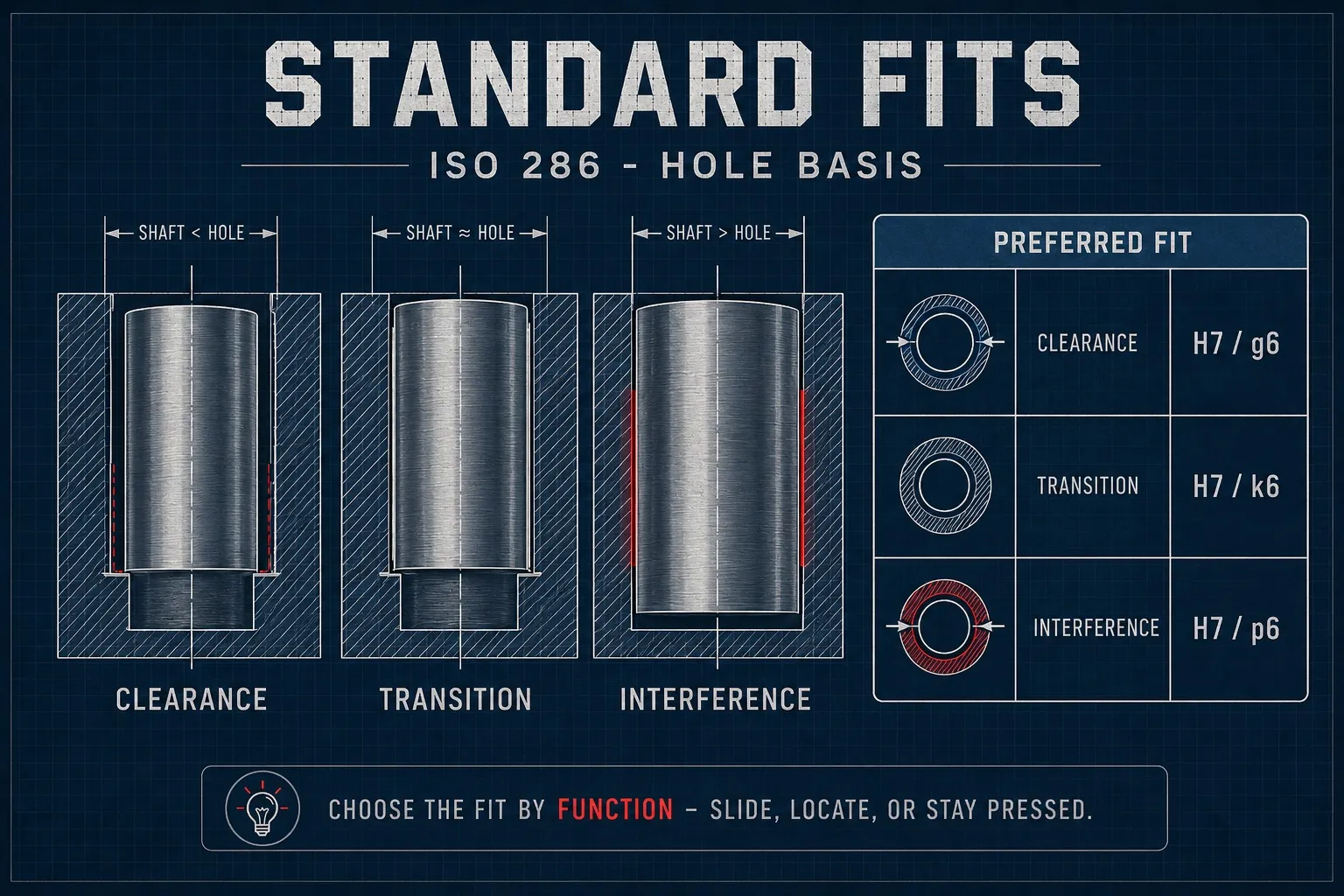
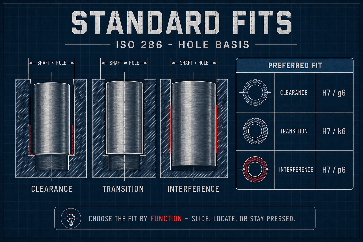
Hole-basis fits from loose running through force-press, with tolerance bands and selection guidance. The reference for picking H7/h6 versus H7/p6 versus H7/s6 when a part calls out a specific functional behavior — clearance, transition, or interference.
Interactive Simulator
ISO 286 Limits & Fits Visualizer
Select an ISO fit designation, adjust the nominal diameter, and slide between manufacturing tolerance limits. See how the hole and shaft tolerance bands align and check the clearance gaps or interference overlaps in real time.
Configuration
One click loads a real-world scenario — then drag the sliders to fine-tune.
Hole Max · Shaft MinMean FitTightest (MMC)
Hole Min · Shaft Max
Calculated Limits
Fitting Schematic
Scale: Highly Exaggerated for ClarityTolerance Band Alignment
Y-Axis: Deviation in Microns (µm)01 · Preferred fits
Hole-basis preferred fits, ISO 286.
Hole-basis means the hole tolerance is fixed (typically H7 or H8) and the shaft tolerance changes to produce the desired fit. The vast majority of mechanical-engineering work in the U.S. and Europe uses hole-basis. Below: the 10 preferred fits per ISO 286, color-coded by category.
| Fit | ISO designation | Type | Description | Typical use |
|---|---|---|---|---|
| Loose running | H11/c11 | Clearance | Wide commercial tolerances. Used for sliding parts that don't need precise alignment. | Linkages, lever pivots, hinge pins |
| Free running | H9/d9 | Clearance | Generous clearance. No accuracy required, just freedom of movement. | Bushings on shafts, low-precision bearings |
| Close running | H8/f7 | Clearance | Running fit at moderate speeds and pressures. Accurate location, free rotation. | Spindle bearings, pilot pins, gear shafts |
| Sliding | H7/g6 | Clearance | Smooth sliding fit. Parts move freely but maintain accurate location. | Sliding gears, drill bushings, sliding shafts |
| Locational clearance | H7/h6 | Clearance | Tightest clearance fit. Hand-assembled, slight clearance for parts that don't move in service. | Locating shafts, dowel-pin sleeves, alignment fits |
| Locational transition (push) | H7/k6 | Transition | Possibly clearance, possibly interference. Hand-assembled with light tap. | Press-fit dowel pins (small), removable sleeves |
| Locational transition (heavy push) | H7/n6 | Transition | Slight interference more common than clearance. Mallet-assembled. | Locating bushings, fixed dowel pins |
| Locational interference (light press) | H7/p6 | Interference | Interference or line-to-line at the limits in this size band. Assembly force depends on actual interference, geometry and material. | Bearing inner rings, fixed bushings |
| Medium drive | H7/s6 | Interference | Heavy interference. Press-fit only. Considerable assembly force. | Coupling on shafts, heavy bushings |
| Force fit | H7/u6 | Interference | Maximum interference. Often requires arbor press or thermal differential (heat hub, freeze shaft). | Permanent gear/wheel-on-shaft, heavy press-fits |
02 · Tolerance bands
Tolerance values — illustrative, over 6 through 10 mm nominal.
The actual tolerance numbers depend on nominal-size band. Below are the values for the over 6 through 10 mm band as a working example. Larger or smaller nominal sizes use proportionally different tolerances — consult ISO 286 (or ANSI B4.2) for your specific size.
| Class | Upper deviation (mm) | Lower deviation (mm) | Role |
|---|---|---|---|
| H11 | +0.090 | 0 | Hole — loose |
| H9 | +0.036 | 0 | Hole — free running |
| H8 | +0.022 | 0 | Hole — close running |
| H7 | +0.015 | 0 | Hole — standard precision |
| h6 | 0 | −0.009 | Shaft — locational clearance |
| g6 | −0.005 | −0.014 | Shaft — sliding |
| f7 | −0.013 | −0.028 | Shaft — close running |
| d9 | −0.040 | −0.076 | Shaft — free running |
| c11 | −0.080 | −0.170 | Shaft — loose running |
| k6 | +0.010 | +0.001 | Shaft — push fit (transition) |
| n6 | +0.019 | +0.010 | Shaft — heavy push (transition) |
| p6 | +0.024 | +0.015 | Shaft — light press (interference) |
| s6 | +0.032 | +0.023 | Shaft — medium drive (interference) |
| u6 | +0.037 | +0.028 | Shaft — force fit (interference) |
Reading: a 10 mm H7 hole has a tolerance of +0.015 / −0.000 mm. Pair it with a 10 mm h6 shaft (+0.000 / −0.009 mm) to get H7/h6 — clearance ranges from 0 mm minimum to 0.024 mm maximum. Pair the same H7 hole with p6 shaft (+0.024 / +0.015) and you get H7/p6 — interference of 0 to 0.024 mm. The math is exactly the same shape; only the shaft offset changes.
03 · Selection rules of thumb
Picking the right fit.
- Default to H7/h6 for accurate location.
When you don’t know what to use, H7/h6 is right ~80% of the time. Locating sleeves, alignment pins, dowel-pin holes — all default to H7/h6.
- For sliding motion, drop the shaft to g6 or f7.
Smooth sliding without play wants H7/g6. Free running with some play, H8/f7. Don’t use H7/h6 for sliding parts — it’ll bind under thermal expansion.
- For press fits, start with p6 and move up.
Light press: H7/p6. Medium drive: H7/s6. Heavy: H7/u6. Going beyond u6 usually requires thermal interference (shrink-fit).
- k6 and n6 are tricky.
Transition fits sometimes give clearance and sometimes interference. Use only when you understand the assembly — they’re intentional in that ambiguity (e.g., dowel pin you want to be either snug or just locating).
- Nominal size matters.
A 10 mm H7 hole has +0.015 / −0.000 mm tolerance. A 100 mm H7 hole has +0.035 / −0.000 mm. Always look up the actual band for your size — don’t scale linearly.
- Inch equivalents are close but not identical.
ANSI B4.1 defines the inch RC/LC/LT/LN/FN classes (Running Clearance, Location Clearance, Location Transition, Location iNterference, Force fit), which map roughly to ISO 286 fits but have different tolerance values; ANSI B4.2 is the metric standard aligned with ISO 286.
Keep exploring
Related tools & references
Achievable tolerances by process and how to call them out.
Worst-case and RSS analysis across a dimension chain.
What each tightening step actually adds to part cost.
How temperature swings shift clearance and interference fits.
CTE values for sizing fits across the operating range.
When position or profile beats a simple ISO fit callout.
Have a part that needs to be made right?
Tell us about your part and we'll get back to you promptly. Aerospace, medical, defense, and semiconductor production work welcome.Email CAD models and drawings to sales@digitalmachine.com, including ITAR, EAR, CUI and AS9100 work. Keep controlled technical data out of web forms.
First articles through full production runs